2017 buick encore manual

This guide provides essential information for 2017 Buick Encore owners, offering a downloadable PDF version of the Owner Manual. Access detailed instructions and support!

Overview of the 2017 Buick Encore

The 2017 Buick Encore represents a compelling entry into the subcompact SUV market, blending practicality with a touch of luxury. This model year continues Buick’s commitment to offering a refined driving experience, featuring a comfortable interior and a suite of available technologies. It’s known for its relatively spacious cabin for its class, making it suitable for small families or individuals seeking extra cargo room.

Powering the 2017 Encore is a 1.4-liter turbocharged four-cylinder engine, paired with a six-speed automatic transmission. Available in various trims, the Encore offers features like a rearview camera, a touchscreen infotainment system, and available safety technologies. Understanding your vehicle through the Owner Manual is crucial for maximizing its benefits and ensuring safe operation.

Importance of the Owner’s Manual

Your 2017 Buick Encore Owner Manual is an indispensable resource, providing vital information for safe and efficient vehicle operation. It details everything from routine maintenance schedules and fluid checks to explanations of dashboard symbols and in-car technology features. Ignoring the manual can lead to improper vehicle use, potentially causing damage or compromising safety.

The manual also outlines warranty details and provides guidance on troubleshooting common issues, like jump-starting procedures or dealing with a flat tire. Specifically, the Canadian edition clarifies substitutions for General Motors of Canada Company. Accessing the PDF version ensures you always have this critical information readily available, empowering you to fully understand and enjoy your Buick Encore.

Where to Find the 2017 Buick Encore Manual (PDF)

Locating your 2017 Buick Encore Owner Manual in PDF format is straightforward. The Buick Owner Center website is the primary source, allowing you to select the year, brand, and model to download the appropriate guide. Several online resources also offer direct links to the PDF, typically around 2MB in size, for free download.

These resources cater to both US and Canadian models, with the Canadian manual specifying General Motors of Canada Company where applicable. Explore Buick’s official channels and reputable automotive websites to ensure you obtain a legitimate and up-to-date copy. Frequently Asked Questions sections often provide direct download links, simplifying the process.

Understanding the Vehicle

Familiarize yourself with the 2017 Buick Encore’s dashboard symbols, instrument panel, and unique features detailed within the comprehensive owner’s manual.

Dashboard Symbols and Indicators

The 2017 Buick Encore’s dashboard utilizes a variety of symbols and indicators to communicate vital vehicle information to the driver. Understanding these alerts is crucial for safe operation and preventative maintenance. The owner’s manual provides a detailed explanation of each symbol, categorizing them by severity – from warning lights requiring immediate attention to informational icons.

Common indicators include the check engine light, oil pressure warning, battery alert, and brake system warning. Familiarize yourself with the meaning of each, as ignoring them could lead to more significant mechanical issues. The manual also clarifies symbols related to safety systems like airbags and seatbelt reminders. Properly interpreting these dashboard cues ensures a confident and informed driving experience with your Buick Encore.

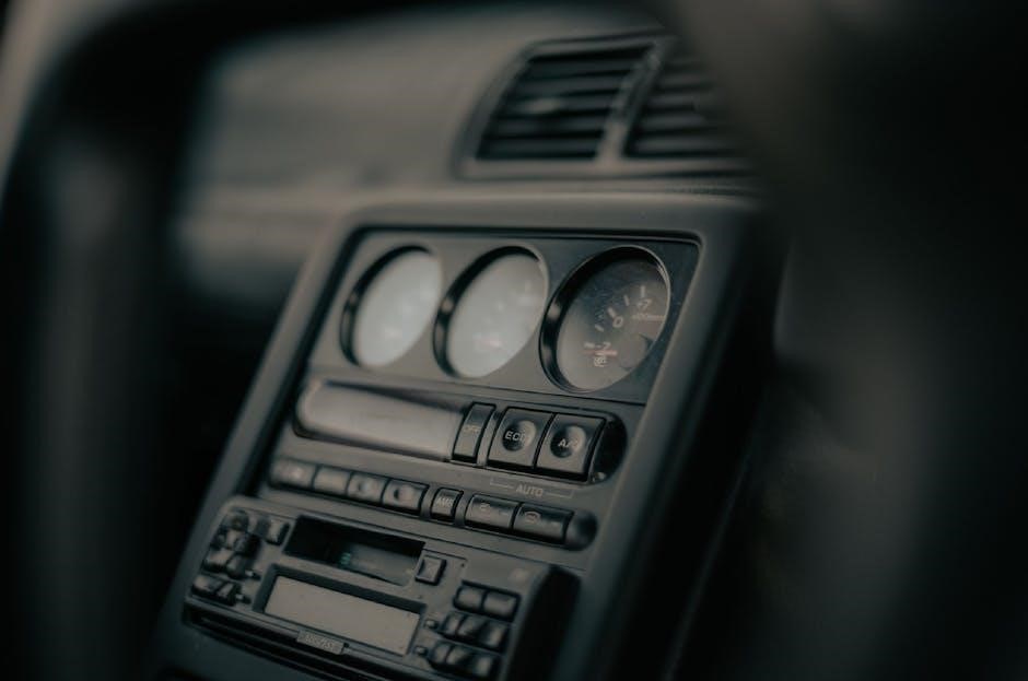
Instrument Panel Overview

The 2017 Buick Encore’s instrument panel is designed for clear and concise delivery of essential driving information. Centrally located, the speedometer and tachometer display vehicle speed and engine RPM. Flanking these are fuel level and engine temperature gauges, providing crucial operational status. A multi-information display screen, configurable by the driver, presents data like trip mileage, average fuel economy, and outside temperature.

Warning lights and indicator icons are prominently positioned for immediate visibility. The manual details the location and function of each element, ensuring drivers can quickly assess vehicle performance. Understanding the layout and available information enhances driver awareness and contributes to a safer, more informed driving experience within the 2017 Buick Encore.

Understanding the Buick Encore’s Features

The 2017 Buick Encore boasts a range of features designed for comfort, convenience, and safety. Key elements include a user-friendly infotainment system with available touchscreen display, offering Bluetooth connectivity for hands-free calling and audio streaming. Available features like keyless entry and remote start enhance convenience, while available safety technologies like rear park assist and side blind zone alert contribute to driver confidence.

The owner’s manual provides detailed explanations of each feature’s operation, customization options, and limitations. Familiarizing yourself with these capabilities allows you to maximize your driving experience and fully utilize the Encore’s potential. Understanding these features ensures safe and efficient operation of your vehicle.

Operating Your Vehicle

The 2017 Buick Encore manual details essential procedures, from starting and stopping the engine to utilizing driving modes and performing routine fluid checks.

Starting and Stopping the Engine

The 2017 Buick Encore’s owner’s manual provides comprehensive instructions for safely starting and stopping the engine. It details the proper use of the ignition system, outlining steps for both traditional key-start and push-button start models, if equipped. The manual emphasizes ensuring the vehicle is in Park or Neutral before starting.

Furthermore, it explains the correct procedure for shutting down the engine, advising against simply turning off the ignition while driving. Detailed guidance is given on what to expect during the starting process, including normal system checks and potential warning indicators. The manual also covers emergency stopping procedures and precautions to take in various driving conditions, ensuring driver awareness and safety.

Driving Modes and Controls

The 2017 Buick Encore manual thoroughly explains the vehicle’s driving modes and control systems. It details the function of the steering wheel controls, including audio, cruise control, and phone operation. The manual clarifies the operation of the gear selector, outlining the differences between Park, Reverse, Neutral, Drive, and any manual shift modes available.

It also provides a detailed overview of the accelerator and brake pedal functions, emphasizing safe driving practices. Information on the available traction control system and stability control system is included, explaining how these features enhance vehicle handling and safety. The manual guides owners on utilizing these controls effectively for optimal performance in various driving scenarios;

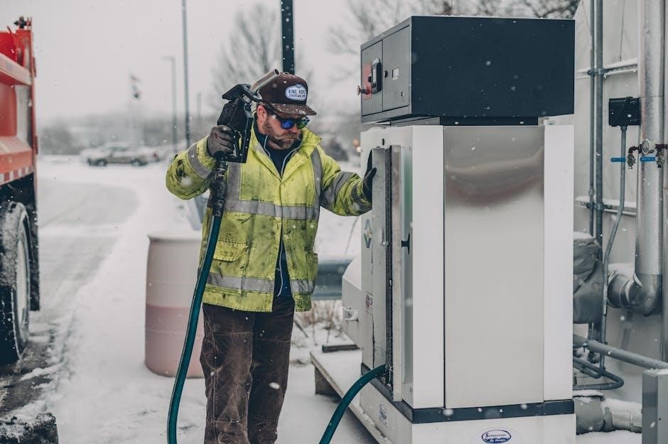
Fueling and Fluid Checks

The 2017 Buick Encore owner’s manual provides comprehensive guidance on proper fueling procedures, including fuel type recommendations and filler door operation. It details how to safely refuel the vehicle and avoid common pitfalls. Crucially, the manual outlines the locations of all essential fluid reservoirs – engine oil, coolant, brake fluid, power steering fluid, and windshield washer fluid.

Step-by-step instructions are given for checking fluid levels accurately, ensuring optimal vehicle performance and longevity. The manual specifies the correct fluid types for each system and provides warnings about the dangers of using incorrect fluids. Regular fluid checks, as outlined in the manual, are vital for preventative maintenance and avoiding costly repairs.

Safety Features

The 2017 Buick Encore manual details critical safety systems, including airbag functionality, seat belt usage guidelines, and proper child safety seat installation procedures.

Airbag System Information

The 2017 Buick Encore’s airbag system is a crucial component of its overall safety design, and the owner’s manual provides detailed information regarding its operation and limitations. Understanding how the airbags deploy – including frontal, side-impact, and curtain airbags – is essential for all occupants.

The manual emphasizes that airbags are designed to supplement seat belts, not replace them. It outlines specific warnings and precautions, such as never placing rear-facing child seats in front of active airbags. Proper seating positions and occupant awareness are highlighted. The guide also explains the system’s sensors and how they determine deployment based on the severity of a collision. Furthermore, it details what to do after airbag deployment, including vehicle inspection and component replacement.

Seat Belt Usage and Safety

The 2017 Buick Encore owner’s manual strongly emphasizes the critical importance of proper seat belt usage for all occupants. It details how to correctly position and adjust seat belts for optimal protection during a collision, covering adults and children alike. The manual clarifies that seat belts are the primary restraint system and work in conjunction with airbags to minimize injury.

Specific instructions are provided regarding lap and shoulder belt usage, as well as the importance of ensuring belts are not twisted or damaged. The guide also addresses seat belt reminders and their function. It stresses that all passengers must be properly restrained on every trip, regardless of distance. Furthermore, the manual outlines legal requirements related to seat belt use and potential penalties for non-compliance, reinforcing its safety message.

Child Safety Seat Installation

The 2017 Buick Encore manual provides detailed guidance on the correct installation of child safety seats, emphasizing adherence to both vehicle instructions and the child seat manufacturer’s guidelines. It illustrates appropriate LATCH (Lower Anchors and Tethers for Children) system usage, detailing anchor point locations within the Encore. The manual also covers installation using the vehicle’s seat belts, ensuring a secure fit.

Specific instructions are given for forward-facing and rear-facing seats, including tether anchor usage for added stability. The guide stresses the importance of verifying proper installation to prevent movement beyond specified limits. It also advises consulting the child seat’s instruction manual for weight and height restrictions. The manual highlights that incorrect installation can significantly reduce the effectiveness of the safety seat in a crash, prioritizing child passenger safety.

Maintenance and Care

The 2017 Buick Encore manual details scheduled maintenance, fluid checks, tire care, and replacement procedures to ensure optimal vehicle performance and longevity.

Scheduled Maintenance

The 2017 Buick Encore’s longevity relies heavily on adhering to the scheduled maintenance outlined in the owner’s manual. This proactive approach prevents costly repairs and ensures optimal performance. Regular inspections cover vital components like fluids, filters, belts, and hoses.

The manual specifies intervals for oil changes, tire rotations, and brake inspections, varying based on driving conditions – normal versus severe duty. Following these guidelines maintains the vehicle’s warranty and resale value. Detailed checklists within the manual guide owners or technicians through each service, ensuring no critical step is overlooked.

Furthermore, the manual highlights the importance of recording maintenance history for future reference and potential buyers. Consistent adherence to the schedule contributes to a safer and more reliable driving experience throughout the Encore’s lifespan.

Tire Pressure and Maintenance

Maintaining correct tire pressure is crucial for the 2017 Buick Encore’s safety, fuel efficiency, and tire lifespan. The owner’s manual details the recommended PSI (pounds per square inch) for both front and rear tires, typically found on a sticker inside the driver’s side doorjamb. Regularly check pressure, especially with temperature changes.

Beyond pressure, the manual emphasizes visual tire inspections for wear and damage – tread depth, sidewall bulges, and uneven wear patterns. Proper tire rotation, as outlined in the scheduled maintenance section, promotes even wear and extends tire life.

The manual also provides guidance on tire replacement, specifying compatible tire sizes and load ratings. Ignoring these recommendations can compromise handling and safety. Consistent tire care contributes to a smoother, safer, and more economical driving experience.

Fluid Levels and Replacements

The 2017 Buick Encore’s optimal performance relies on maintaining correct fluid levels. The owner’s manual details how to check engine oil, coolant, brake fluid, power steering fluid, and windshield washer fluid. Regular checks prevent damage and ensure proper function.

The manual specifies replacement intervals for each fluid, based on driving conditions and mileage. Ignoring these intervals can lead to component failure. It outlines the correct fluid types to use – crucial for avoiding compatibility issues.

Detailed instructions guide owners through the fluid replacement process, or when to seek professional service. Proper fluid maintenance extends the vehicle’s lifespan and maintains its reliability, contributing to a safe and enjoyable driving experience.

In-Car Technology

Explore the 2017 Buick Encore’s infotainment system, Bluetooth pairing, and navigation features through the owner’s manual’s detailed guides and instructions.

Infotainment System Guide

The 2017 Buick Encore’s infotainment system is a central hub for connectivity and entertainment. This guide, found within the owner’s manual, details operation of the touchscreen display, radio functions, and available apps. Learn how to customize your settings, access vehicle information, and manage audio sources.

The manual provides step-by-step instructions for navigating the menus, understanding icons, and utilizing voice commands. It also covers smartphone integration features, allowing seamless access to calls, messages, and music. Troubleshooting tips are included for common issues, ensuring a smooth and enjoyable in-car experience. Familiarize yourself with the system’s capabilities to maximize convenience and safety while driving;

Bluetooth Pairing and Usage

The 2017 Buick Encore’s Bluetooth system enables hands-free calling and wireless audio streaming. The owner’s manual provides a detailed guide to pairing your smartphone or other compatible device. It explains the initial setup process, including entering pairing codes and granting access permissions.

Once connected, you can make and receive calls directly through the vehicle’s speakers, and enjoy your favorite music wirelessly. The manual also covers managing paired devices, troubleshooting connection issues, and understanding Bluetooth profiles. Learn how to utilize voice commands for hands-free operation, enhancing safety and convenience. Detailed instructions ensure a seamless integration of your mobile devices with your Encore.

Navigation System Instructions

The 2017 Buick Encore’s navigation system, detailed in the owner’s manual, offers turn-by-turn directions and points of interest. The manual guides users through initial setup, including map updates and entering destination addresses. It explains how to utilize the touchscreen interface for zooming, panning, and route customization.

Learn to input addresses, search for specific locations, and save frequently visited destinations. The guide also covers advanced features like real-time traffic updates and alternative route suggestions. Troubleshooting tips address common issues, such as GPS signal loss or incorrect map displays. Understanding the system’s voice guidance and safety features ensures a confident and efficient navigation experience during your travels.

Troubleshooting Common Issues

The 2017 Buick Encore manual offers solutions for jump starts, flat tires, and deciphering warning lights, ensuring quick responses to vehicle problems.

Jump Starting Procedures

If your 2017 Buick Encore battery is depleted, a jump start can get you moving again. The owner’s manual details a safe procedure, emphasizing proper cable connection order – positive to positive, negative to a grounded metal surface on your vehicle, not the battery.

Ensure both vehicles are off before connecting cables. After the jump, let the receiving vehicle run for a period to recharge the battery. The manual cautions against incorrect procedures, which could damage electrical systems. It’s crucial to follow the outlined steps precisely for a successful and safe jump start. Always consult the manual for specific diagrams and warnings related to your Buick Encore.

Dealing with Flat Tires

The 2017 Buick Encore owner’s manual provides comprehensive guidance on handling a flat tire. It details locating the spare tire, jack, and tools, typically found in the vehicle’s storage area. The manual stresses safety first – pulling over to a level, stable surface away from traffic is paramount.

Step-by-step instructions illustrate proper jacking points and lug nut loosening/tightening sequences. It’s vital to follow these instructions carefully to avoid vehicle damage or personal injury. The manual also covers tire changing best practices and emphasizes checking the spare tire’s pressure. Finally, it recommends professional tire repair or replacement as soon as possible after using the spare.

Warning Light Meanings and Actions

The 2017 Buick Encore’s instrument panel features various warning lights, each signaling a potential issue. The owner’s manual meticulously details each light’s meaning, ranging from minor maintenance reminders to critical system failures. Ignoring these lights can lead to more significant problems.

Lights are categorized by severity – some require immediate attention (like the oil pressure or engine temperature warning), while others indicate a need for scheduled service. The manual provides specific actions to take for each light, such as safely pulling over, checking fluid levels, or contacting a Buick service center. Understanding these signals ensures proactive vehicle care and prevents potential damage.

Specific 2017 Encore Details

The 2017 Buick Encore manual notes differences from other years and includes specifics for Canadian models, alongside comprehensive warranty information for owners.

Differences from Other Encore Years

The 2017 Buick Encore experienced subtle, yet notable, refinements compared to preceding model years. While maintaining the core appeal of its compact SUV design, the 2017 version often featured updated infotainment system capabilities and potentially minor adjustments to standard equipment packages. Owners referencing the owner manual will discover details regarding these changes.

Specifically, some reports indicate enhancements to the available safety features and connectivity options. It’s crucial to consult the 2017 specific PDF manual to understand these distinctions. Earlier models might lack certain features present in the 2017 version, impacting functionality and user experience. The manual clearly outlines these variations, ensuring owners are fully aware of their vehicle’s capabilities and how they differ from previous Buick Encore iterations.

Canadian Model Specifics

The 2017 Buick Encore owner manual for vehicles first sold in Canada contains crucial distinctions. It explicitly instructs owners to substitute “General Motors of Canada Company” for “Buick Motor Division” throughout the entire manual. This legal clarification ensures accurate representation of the responsible entity for warranty and service within Canada.

Furthermore, Canadian models may exhibit variations in standard equipment, emissions compliance, and regulatory adherence compared to their US counterparts. The PDF version of the owner’s manual details these specific adaptations. Owners should carefully review the manual to understand any unique requirements or features applicable to their Canadian-market 2017 Encore, ensuring proper operation and maintenance aligned with Canadian regulations.

Warranty Information

The 2017 Buick Encore is covered by a comprehensive warranty, details of which are thoroughly outlined within the owner manual’s dedicated section. This includes coverage for defects in materials or workmanship, specifying timeframes and mileage limitations for various components.

The manual clarifies what is covered under the basic vehicle warranty, powertrain warranty, and corrosion protection warranty. It also details what is not covered, such as wear-and-tear items or damage resulting from improper maintenance. Owners can find specific claim procedures and contact information for Buick customer support within the PDF document. Understanding these warranty terms is crucial for maximizing vehicle protection and ensuring eligible repairs are handled efficiently.

Additional Resources

Explore the Buick Owner Center website for FAQs, downloadable manuals, and direct access to Buick customer support for your 2017 Encore.

Buick Owner Center Website

The Buick Owner Center website serves as a comprehensive online resource for all 2017 Buick Encore owners. It provides convenient access to digital versions of your Owner Manual, allowing you to quickly find information about your vehicle’s features and operation. Beyond the manual, the website offers a wealth of helpful guides and resources designed to enhance your ownership experience.

You can register your vehicle on the site to receive important updates, recalls, and exclusive offers. The Buick Owner Center also features a frequently asked questions (FAQ) section addressing common concerns and troubleshooting tips. Furthermore, it streamlines access to Buick customer support, enabling you to connect with representatives for personalized assistance. It’s a central hub for everything 2017 Encore related!

Frequently Asked Questions (FAQ)

Many common questions regarding the 2017 Buick Encore are addressed in readily available FAQs. Users often inquire about locating the digital Owner Manual, specifically the PDF version for easy download and access. Another frequent question concerns compatibility with different mobile devices for viewing the manual.

Troubleshooting basic issues, like resetting the maintenance light or understanding specific dashboard symbols, also generates numerous inquiries. Owners frequently ask about differences between 2017 models and other Encore years. If you can’t find the answer to your specific question within the manual itself, the FAQ section is a great starting point before contacting Buick customer support for further assistance.

Contacting Buick Customer Support

If the 2017 Buick Encore Manual and online resources don’t resolve your query, Buick Customer Support is available to assist. Direct contact options provide personalized help with vehicle-specific concerns. While specific contact details may vary, the Buick Owner Center website is the primary hub for support information.

You can typically find phone numbers and online chat features for immediate assistance. When contacting support, having your vehicle’s VIN readily available will expedite the process. Be prepared to describe your issue clearly and concisely. Remember to reference the 2017 Encore model year for accurate guidance. Dedicated representatives are equipped to address questions related to the Owner Manual and vehicle operation.

manual walkie talkie motorola

Motorola Talkabout owners manuals provide comprehensive guidance for safe and effective use. Essential reading includes the RF Energy Exposure and Product Safety Guide.

These manuals detail features like turning radios on/off, volume adjustment, and proper communication protocols for optimal performance across various Motorola models.

What are Motorola Walkie Talkies?

Motorola walkie talkies, often called two-way radios, are portable communication devices enabling direct voice transmission. Motorola Talkabout models, detailed in their respective owners manuals, offer license-free operation for personal use. These devices utilize radio frequencies to transmit and receive signals, allowing real-time conversations without relying on cellular networks.

The manuals emphasize understanding RF energy exposure guidelines for safe operation. Key features, like channel selection and the push-to-talk (PTT) function, are thoroughly explained. They are ideal for recreational activities, events, and situations where reliable, immediate communication is crucial, offering a dependable alternative to mobile phones in areas with limited coverage.

Brief History of Motorola Two-Way Radios

Motorola’s pioneering work in two-way radio began in 1928 with the development of police mobile radios, revolutionizing public safety communication. This innovation evolved into portable handheld radios, precursors to today’s walkie talkies. Throughout the decades, Motorola consistently advanced radio technology, focusing on improved signal clarity, range, and durability.

The Talkabout series, documented in detailed owners manuals, represents Motorola’s commitment to accessible communication. These manuals reflect a history of user-focused design. From early emergency services to recreational use, Motorola radios have remained a trusted communication tool, continually adapting to meet evolving needs.

Understanding Key Features

Motorola walkie talkie manuals highlight essential features like channel selection, PTT functionality, and squelch control, ensuring clear and reliable communication for all users.

Channel Selection and Frequency

Motorola walkie talkie manuals emphasize the importance of all radios within a group being set to the same channel for successful communication; These manuals detail how to select channels, often using a rotating dial or button presses.

Understanding frequency is crucial; manuals explain how channels correlate to specific frequencies, impacting range and potential interference. Some models offer pre-programmed channels, while others allow for custom frequency programming. Proper channel selection minimizes interference and ensures clear transmissions, as detailed within the owner’s guides.

Push-to-Talk (PTT) Functionality

Motorola walkie talkie manuals consistently highlight the Push-to-Talk (PTT) button as the primary method for initiating transmissions. Before speaking, users must press and hold the PTT button, activating the microphone and sending their voice.

Releasing the PTT button switches the radio back to receive mode. Manuals often include troubleshooting tips for PTT button issues, such as ensuring it’s fully depressed or checking for obstructions. Effective PTT usage, as described in the guides, is vital for clear, two-way communication.

Squelch Control Explained

Motorola walkie talkie manuals detail squelch control as a feature minimizing unwanted background noise. Squelch settings determine the signal strength required to open the speaker. Lower settings increase sensitivity, capturing weaker signals but also more noise.

Higher settings reduce noise but may block faint transmissions. Manuals advise adjusting squelch to find a balance between clarity and signal reception. Proper squelch adjustment, as outlined in the guides, enhances communication quality by filtering out static and interference, improving overall usability.

Setting Up Your Motorola Walkie Talkie

Motorola manuals emphasize proper battery installation and powering on. Users should then program channels and scan for available frequencies, adjusting volume for clear communication.

Installing Batteries and Powering On

Motorola walkie-talkie manuals consistently highlight the importance of correct battery installation for optimal performance and longevity. Typically, this involves locating the battery compartment, inserting batteries with the correct polarity (as indicated inside the compartment), and securing the cover.

To power on the radio, users generally need to press and hold the MENU/Power button. The manual details that a visual or auditory cue confirms successful activation. Always refer to your specific model’s manual, like the Talkabout T42, for precise instructions, as procedures can vary slightly between different Motorola radios.

Channel Programming and Scanning

Motorola walkie-talkie manuals emphasize the significance of channel selection for clear communication. To program channels, users typically navigate the menu system using the buttons, referencing the specific instructions in their model’s guide – such as the Talkabout T5900.

Scanning functionality allows the radio to automatically search for active channels. The manual details how to initiate a scan, and explains that the radio will pause on any detected transmissions. Proper channel programming and scanning ensure effective communication within a group, avoiding interference and maximizing range.

Setting Volume Levels

Motorola walkie-talkie manuals clearly illustrate how to adjust the volume for comfortable listening. Typically, dedicated “+” and “-” buttons control the audio output, as detailed in the Talkabout T42 owner’s manual;

Users should adjust the volume to a level that allows clear reception without distortion, considering the surrounding environment. Maintaining appropriate volume levels is crucial for effective communication and prevents missed transmissions. The manual also advises testing the volume with another radio to ensure audibility for all group members.

Using Your Walkie Talkie Effectively

Motorola manuals emphasize setting all radios to the same channel for communication. Proper etiquette and understanding range limitations are also key for optimal use.

Proper Communication Etiquette

Motorola walkie-talkie manuals consistently highlight the importance of clear and concise communication. Before transmitting, always identify yourself to ensure everyone knows who is speaking. Utilize a brief, pre-agreed upon signal – like “Over” – to indicate you’ve finished speaking and are awaiting a response;

Avoid lengthy monologues; keep transmissions short and to the point, allowing others a chance to contribute. Refrain from using jargon or codes unfamiliar to all parties. Respect channel usage and avoid unnecessary chatter, especially in emergency situations. Following these guidelines ensures efficient and effective communication for all users.

Range and Signal Strength Considerations

Motorola walkie-talkie manuals emphasize that stated range is maximized in optimal conditions – clear line of sight, unobstructed terrain. Actual range is significantly impacted by obstacles like buildings, trees, and hills. Signal strength diminishes with distance and interference.

To maximize range, maintain a clear line of sight whenever possible. Higher antenna placement can improve signal transmission and reception. Be aware that weather conditions can also affect performance. Regularly check signal strength indicators and adjust channels or locations as needed for reliable communication.

Troubleshooting Common Issues

Motorola walkie-talkie manuals address frequent problems. If no power or sound occurs, check battery installation and ensure the volume is adjusted. Poor reception often stems from obstructions or being out of range; relocate or change channels. PTT button malfunctions may require battery removal/reinstallation.

Consult the manual for specific model troubleshooting steps. Interference from other devices can also cause issues. Resetting the radio to factory defaults is a last resort. If problems persist, refer to Motorola’s support website or online forums for assistance.

Safety Information and Guidelines

Motorola manuals emphasize reading the RF Energy Exposure and Product Safety Guide before use. This ensures understanding of operating temperatures and battery safety precautions.

RF Energy Exposure and Product Safety

Motorola walkie-talkie manuals consistently prioritize user safety, beginning with a dedicated RF Energy Exposure and Product Safety Guide. This crucial document details essential information regarding exposure to radio frequency energy, adhering to established safety standards.

Understanding these guidelines is paramount before operating the device. The manual outlines specific operational instructions designed to minimize exposure and ensure responsible use. It covers topics like appropriate antenna handling, maintaining a safe distance during transmission, and awareness of potential interference. Following these recommendations safeguards both the user and those nearby, promoting a secure communication experience with your Talkabout radio.

Operating Temperature and Environmental Factors

Motorola walkie-talkie manuals emphasize the importance of operating conditions for optimal performance and longevity. These guides detail acceptable temperature ranges for both charging and usage, typically outlining limits for extreme heat or cold.

Environmental factors, such as humidity and exposure to dust or water, are also addressed. Manuals advise against operating the radios in excessively damp or corrosive environments. Proper care, including avoiding direct sunlight and protecting the device from rain, is crucial. Adhering to these guidelines ensures reliable operation and prevents potential damage to your Talkabout radio.

Battery Safety Precautions

Motorola walkie-talkie manuals prioritize battery safety, providing crucial guidelines for users. These manuals strongly advise against disassembling or modifying the battery pack, as this can pose a risk of fire or chemical exposure.

Proper charging procedures are detailed, emphasizing the use of Motorola-approved chargers only. Avoid extreme temperatures during charging and storage. Damaged batteries should be immediately replaced and disposed of responsibly, following local regulations. The manuals also caution against short-circuiting the battery terminals, ensuring safe operation of your Talkabout device.

Specific Motorola Models & Manuals

Motorola offers diverse models like the T42, T5900, and GP2000s Alpha, each with dedicated owners manuals available for download and online access.

Motorola Talkabout T42 Manual Overview

The Motorola Talkabout T42 Owners Manual is a crucial resource for users, prioritizing safety and operational understanding. It begins with essential RF Energy Exposure and Product Safety guidelines, detailing responsible radio usage. Key sections cover powering the device on and off, utilizing the MENU button, and precisely adjusting volume levels with dedicated buttons.

The manual emphasizes the importance of all radios within a group being set to the same channel for successful communication. It provides clear instructions on holding the radio correctly during both talking and listening, ensuring optimal signal transmission and reception. This manual serves as a comprehensive guide for maximizing the T42’s functionality.

Motorola Talkabout T5900 User Guide

Accessing the Motorola Talkabout T5900 user manual is facilitated through resources like the Internet Archive, offering free download, borrowing, and streaming options. This guide provides detailed instructions for operating the T5900, ensuring users can fully utilize its features. The availability through the Internet Archive promotes accessibility and preservation of valuable product information.

Users are encouraged to support the Internet Archive’s mission by considering donations, respecting their privacy policy, and acknowledging that information is not sold or traded. The manual itself covers all aspects of T5900 operation, from basic functions to advanced settings, empowering users with comprehensive knowledge.

Motorola GP2000s Alpha Manual Details

The Motorola GP2000s Alpha walkie-talkie manual, available on platforms like ManualLib, is a comprehensive resource for users and technicians. This collection of manuals provides detailed information on the radio’s operation, maintenance, and troubleshooting procedures. The manual’s item size is 11.3MB, added to the archive on January 6, 2022.

It’s identified by a unique identifier, ensuring easy retrieval. This resource is invaluable for understanding the GP2000s Alpha’s functionalities, offering insights into its technical specifications and operational characteristics, aiding in effective use and repair.

Advanced Features & Settings

Motorola walkie-talkie manuals explain advanced settings like VOX, call tones, and privacy codes, enhancing communication flexibility and security for users.

VOX (Voice Operated Exchange) Function

Motorola walkie-talkie manuals detail the Voice Operated Exchange (VOX) function, enabling hands-free communication. This feature automatically transmits when sound is detected, eliminating the need to press the PTT button. Manuals explain how to adjust VOX sensitivity levels to suit different environments, minimizing false activations from background noise.

Proper VOX setup, as outlined in the guides, ensures clear transmissions and convenient operation. Users learn to balance sensitivity for reliable activation while avoiding unwanted broadcasts. The manuals also cover potential interference and troubleshooting steps related to the VOX functionality, maximizing its usability.

Call Tones and Privacy Codes

Motorola walkie-talkie manuals explain the use of call tones and privacy codes to enhance communication. Call tones signal to others before transmitting, while privacy codes (CTCSS/DCS) limit reception to radios set to the same code, reducing interference. Manuals detail how to select and program these features for clearer, more secure conversations.

Understanding these settings, as described in the guides, allows users to minimize unwanted interruptions and maintain privacy. The manuals clarify that privacy codes don’t offer complete security, but improve clarity in crowded environments. Proper configuration ensures effective communication within a designated group.

Monitor Function Explained

Motorola walkie-talkie manuals detail the ‘Monitor’ function, bypassing the squelch control to hear all radio activity on the current channel, even weak signals. This feature, explained in user guides like those for the Talkabout series, is useful for checking channel clarity before transmitting or detecting distant, faint transmissions.

Manuals caution that continuous monitoring drains battery life. It’s recommended for brief checks only. The function temporarily disables privacy codes, allowing reception of all signals. Understanding its purpose, as outlined in the documentation, enhances effective radio operation and troubleshooting.

Maintenance and Care

Motorola walkie-talkie manuals emphasize regular cleaning, proper battery charging/storage, and careful antenna handling to ensure optimal performance and longevity of your device.

Cleaning Your Walkie Talkie

Motorola walkie-talkie manuals consistently recommend regular cleaning to maintain optimal functionality and hygiene. Before cleaning, always remove the batteries to prevent accidental activation and potential damage. Use a soft, damp cloth to wipe down the exterior casing, avoiding harsh chemicals or abrasive cleaners that could scratch the surface or damage internal components.

Pay particular attention to the speaker grill and microphone port, gently removing any dust or debris. For stubborn dirt, a slightly moistened cotton swab can be used. Ensure the walkie-talkie is completely dry before reattaching the batteries and resuming operation. Avoid immersing the device in water or any liquid.

Battery Charging and Storage

Motorola walkie-talkie manuals emphasize proper battery care for longevity and performance. Utilize only the charger specifically designed for your model to avoid damage. Charging times vary; consult your manual for specifics. Avoid overcharging, as it can reduce battery lifespan. When storing for extended periods, remove the batteries to prevent corrosion and potential leakage.

Store batteries in a cool, dry place, away from direct sunlight and extreme temperatures. Rechargeable batteries should be partially charged before long-term storage. Always refer to the manual for specific battery type recommendations and disposal guidelines.

Antenna Care and Replacement

Motorola walkie-talkie manuals highlight the antenna’s crucial role in signal transmission and reception. Regularly inspect the antenna for any signs of damage, such as bends, cracks, or corrosion. Avoid forceful bending or twisting, as this can compromise its performance. If the antenna becomes damaged, it should be replaced promptly.

Use only Motorola-approved replacement antennas to ensure compatibility and optimal functionality. Improperly installed or incompatible antennas can reduce range and potentially damage the radio. Consult your manual for specific antenna replacement instructions and safety precautions.

Troubleshooting Common Problems

Motorola walkie-talkie manuals address issues like no power, poor reception, or PTT button malfunctions, offering step-by-step solutions for quick resolution.

No Power or Sound

Motorola walkie-talkie manuals frequently address the issue of no power or sound. First, verify correct battery installation and ensure batteries aren’t depleted; replace if necessary. Confirm the radio is switched on by pressing and holding the MENU/power button.

If power is present, check the volume level using the up and down buttons. Ensure the squelch level isn’t set too high, blocking weak signals. Consult the manual for specific troubleshooting steps related to your model, like the T42 or GP2000s Alpha, as procedures can vary. A reset might also resolve the issue.

Poor Reception or Range

Motorola walkie-talkie manuals highlight several causes for poor reception or limited range. Obstacles like buildings, trees, and terrain significantly impact signal strength. Ensure all radios in your group are set to the same channel for clear communication.

Verify antenna connections are secure and undamaged; a damaged antenna drastically reduces range. Lowering the squelch level (consult your T42 or GP2000s Alpha manual) can help receive weaker signals. Interference from other devices may also be a factor. Try relocating to a more open area for improved performance.

PTT Button Issues

Motorola walkie-talkie manuals address potential Push-to-Talk (PTT) button malfunctions. A common issue is a sticky or unresponsive button, often caused by dirt or debris. Carefully clean around the button with a soft, dry cloth – avoid liquids;

If the PTT button still doesn’t function correctly, consult the T5900 user guide or the specific manual for your model (like the GP2000s Alpha). Some models may have programmable PTT settings. Ensure the button isn’t locked or assigned to an unintended function. If problems persist, professional repair may be necessary.

Resources and Support

Motorola’s support website offers extensive resources, including downloadable manuals for models like the T42 and GP2000s Alpha. Online forums and communities also provide assistance.

Motorola Support Website

Motorola’s official support website serves as a central hub for accessing a wealth of information regarding their walkie-talkie products. Users can directly download comprehensive owner’s manuals for a vast range of Talkabout models, including the popular T42 and more advanced options like the T5900.

Beyond manuals, the website provides FAQs, troubleshooting guides, and safety information, such as the crucial RF Energy Exposure and Product Safety Guide. It’s a valuable resource for resolving common issues and understanding the full capabilities of your Motorola two-way radio, ensuring optimal and safe operation.

Online Forums and Communities

Numerous online forums and communities dedicated to two-way radios offer invaluable support for Motorola walkie-talkie users. These platforms provide a space to connect with fellow enthusiasts, share experiences, and seek assistance with specific models like the GP2000s Alpha or Talkabout series.

Users frequently discuss manual interpretations, troubleshooting tips beyond the official documentation, and modifications. These communities are excellent resources for finding solutions to unique problems and gaining deeper insights into maximizing the functionality of your Motorola radio, complementing the official manuals.

Finding Replacement Parts

Locating replacement parts for your Motorola walkie-talkie can extend its lifespan and maintain optimal performance. While Motorola’s official support website is a primary resource, numerous third-party retailers specialize in two-way radio components.

When searching, having your specific model number (like T42 or T5900) from the owner’s manual is crucial. Common replacements include antennas, batteries, and speaker microphones. Online marketplaces and specialized radio supply stores often carry these parts, ensuring continued functionality of your trusted communication device.

weber spirit e 310 user manual

Weber Spirit E-310 User Manual: A Comprehensive Guide

This comprehensive guide details the Weber Spirit E-310, offering assembly, operation, maintenance, and troubleshooting instructions․ Access manuals and diagrams online for optimal grilling!

Welcome to the world of Weber grilling! The Spirit E-310 is a popular gas grill known for its reliability and performance․ This manual serves as your guide to safely and effectively using your new grill․ Whether you’re a seasoned grill master or a beginner, understanding its features is key․

Detailed instructions, exploded views, and parts lists are readily available online, ensuring a smooth assembly and maintenance experience․ Explore the manual to unlock the full potential of your Weber Spirit E-310․

Understanding the Grill Components

The Weber Spirit E-310 comprises several key components working in harmony․ These include the robust grill cart and body providing stability, durable cooking grates for optimal heat distribution, and flavorizer bars that vaporize drippings for enhanced flavor․

The burners and ignition system are crucial for starting and controlling the heat․ Familiarizing yourself with each part, referencing exploded view diagrams, will aid in assembly and future maintenance, as detailed in the manual․

Grill Cart and Body

The Weber Spirit E-310’s cart and body are constructed for durability and stability during grilling․ The cart provides a solid base, often featuring convenient side tables for prep work and tool storage․ The body, typically porcelain-enameled, protects against rust and corrosion, ensuring longevity․

Carefully follow the manual’s assembly instructions to securely attach all cart components․ Proper assembly is vital for safe and enjoyable grilling experiences, supporting the weight of the grill and its contents․

Cooking Grates and Flavorizer Bars

Weber Spirit E-310 cooking grates, typically porcelain-enameled cast iron, distribute heat evenly for optimal cooking․ Flavorizer bars sit below the grates, vaporizing drippings to infuse food with smoky flavor while protecting burners․

The manual details proper grate cleaning and seasoning to prevent sticking and rust․ Regularly inspect Flavorizer bars, replacing them when worn, as they are crucial for flavor and grill longevity․

Burners and Ignition System

Weber Spirit E-310 burners are stainless steel, providing consistent and reliable heat․ The manual outlines cleaning procedures to prevent clogging and ensure optimal performance․ The ignition system, typically push-button, requires periodic maintenance for consistent sparking․

Troubleshooting steps for a grill that won’t light are detailed, including checking gas supply and burner ports․ Proper burner function is vital for efficient cooking and even heat distribution․

Assembly Instructions Overview

The Weber Spirit E-310 requires assembly, detailed in the included Installation Manual․ Carefully follow each step, referencing the exploded view diagrams for component placement․ Ensure all parts are present before beginning․

The manual emphasizes proper tightening of screws and bolts for stability․ A successful assembly guarantees safe and efficient operation of your new grill․ Online resources and videos can supplement the printed instructions․

Step-by-Step Assembly Guide

Begin by attaching the legs to the grill cart, ensuring secure fastening with provided hardware․ Next, assemble the side shelves and attach them to the cart․ Carefully install the flavorizer bars and cooking grates, aligning them correctly․

Connect the burners and verify proper ignition functionality․ Finally, attach the grease management system․ Refer to the exploded view diagrams for visual guidance throughout the process․ Double-check all connections for safety․

Tools Required for Assembly

For successful assembly of your Weber Spirit E-310, you’ll need a Phillips head screwdriver, a flathead screwdriver, and an adjustable wrench․ A rubber mallet can be helpful for gently securing components․

While not essential, a power drill with appropriate bits can expedite the process․ Ensure you have a level to guarantee a stable grill setup․ Always prioritize using the correct tools to prevent damage to parts during installation․

First-Time Use and Seasoning

Before your inaugural cookout, perform a crucial burn-off․ Ignite all burners on high for about 15-20 minutes with the lid closed․ This eliminates manufacturing residues․

Next, season the cooking grates․ Lightly coat them with high-heat cooking oil after the burn-off․ This prevents food from sticking and protects against rust․ Proper seasoning ensures optimal performance and longevity of your Weber Spirit E-310․

Initial Burn-Off Procedure

The initial burn-off is essential for removing oils and residues from the manufacturing process․ Open the grill lid and turn all burners to the highest setting․ Allow the grill to run for approximately 15 to 20 minutes․

This process will create some smoke and odor, which is normal․ Ensure adequate ventilation․ After the burn-off, your Weber Spirit E-310 is ready for seasoning the cooking grates, preparing it for delicious meals!

Seasoning the Cooking Grates

Seasoning the grates creates a natural, non-stick surface, preventing food from sticking and protecting against rust․ After the initial burn-off, reduce the burners to medium-high heat․

Apply a thin coat of high-heat cooking oil to the grates using a paper towel or brush․ Continue heating for 15-20 minutes, then allow to cool․ Repeat this process for optimal seasoning, ensuring your Weber Spirit E-310 is ready for grilling!

Operating Instructions

Operating your Weber Spirit E-310 is straightforward․ Begin by ensuring the grill lid is open․ Turn on the gas supply and follow the lighting instructions․ Adjust the burner control knobs to achieve your desired cooking temperature․

Always preheat the grill for 10-15 minutes before cooking․ Monitor the lid thermometer for accurate temperature readings․ Remember to close the lid while cooking for even heat distribution and efficient grilling!

Lighting the Grill

Lighting your Weber Spirit E-310 is simple․ First, fully open the grill lid․ Turn the gas supply on․ Then, open the side burner valve slightly․ Press the electronic ignition button repeatedly, observing for a steady flame․

If it doesn’t light after several attempts, turn off the gas, wait five minutes, and try again․ Always ensure proper ventilation during lighting․ Never lean over the grill when igniting!

Adjusting Burner Control Knobs

Adjusting the burner control knobs on your Weber Spirit E-310 allows precise temperature control․ Rotate the knobs clockwise to increase the flame and heat, and counterclockwise to decrease it․

Each knob corresponds to a specific burner․ Start with a low setting and gradually increase as needed․ Remember, preheating takes time! Consistent monitoring ensures optimal cooking temperatures for various recipes․

Preheating the Grill

Preheating your Weber Spirit E-310 is crucial for successful cooking․ Turn all burner control knobs to the high position and allow the grill to heat for 10-15 minutes․

A properly preheated grill ensures even cooking and helps prevent food from sticking․ Use the built-in thermometer to monitor the internal temperature․ Once the desired temperature is reached, adjust the burners accordingly for your recipe․

Cooking Tips and Techniques

Mastering your Weber Spirit E-310 involves understanding cooking methods․ Direct cooking, with burners on high, is ideal for searing steaks and quick meals․ Indirect cooking, with burners on low or off, suits larger cuts and slower roasting․

Temperature control is key; utilize the lid thermometer and burner knobs․ Experiment with different heat zones for versatile grilling․ Remember, practice makes perfect!

Direct vs․ Indirect Cooking

Direct cooking on your Weber Spirit E-310 involves placing food directly over lit burners, achieving high heat for searing steaks, burgers, and vegetables quickly․ Indirect cooking utilizes the grill as an oven, with burners on low or off, circulating heat for roasting chicken or ribs․

Understanding these techniques expands your culinary possibilities․ Experiment with both methods to discover the best approach for various foods and desired results!

Temperature Control and Monitoring

Weber Spirit E-310 temperature control relies on adjusting burner knobs and utilizing the lid thermometer․ Preheating ensures even cooking, while monitoring internal food temperature with a meat thermometer is crucial for safety and desired doneness;

Experiment with burner settings to achieve specific heat levels․ Remember, consistent temperature management is key to grilling success, yielding perfectly cooked meals every time!

Cleaning and Maintenance

Regular cleaning extends the life of your Weber Spirit E-310․ After each use, burn off residue on high heat․ Periodically clean cooking grates with a grill brush, and scrape flavorizer bars to remove buildup․

Inspect burners for clogs and clean as needed․ A clean grill ensures optimal performance and prevents flare-ups․ Consistent maintenance guarantees years of enjoyable grilling experiences!

Cleaning Cooking Grates

After each grilling session, allow the cooking grates to cool slightly․ Use a sturdy grill brush to remove food particles and debris․ For stubborn residue, a paste of baking soda and water can be effective․

Avoid abrasive cleaners that could damage the grates’ finish․ Regularly cleaning the grates prevents flare-ups and ensures flavorful cooking․ Properly maintained grates contribute to a superior grilling experience․

Cleaning Flavorizer Bars

Regularly cleaning Flavorizer bars is crucial for optimal grill performance․ Remove the bars and scrape off accumulated grease and food debris with a putty knife or scraper․ Wash them with warm, soapy water, and a mild degreaser if needed․

Inspect for excessive wear or damage, replacing them when necessary․ Clean Flavorizer bars prevent flare-ups and vaporize drippings, enhancing flavor․ Maintaining these bars ensures a consistently delicious grilling experience․

Cleaning the Burners

Proper burner cleaning ensures efficient gas flow and consistent heating․ Turn off the gas supply and remove the cooking grates and Flavorizer bars․ Carefully detach the burners and inspect the ports for blockages․

Use a wire brush or pipe cleaner to clear any debris․ A mild solvent can help dissolve stubborn residue․ Reinstall the burners securely, verifying proper alignment․ Clean burners contribute to even cooking and optimal grill performance․

Troubleshooting Common Issues

Facing problems with your Weber Spirit E-310? Common issues include difficulty lighting and uneven heating․ For a grill that won’t light, check the gas supply, igniter battery, and burner ports․

Uneven heating often stems from blocked burners or uneven Flavorizer bar placement․ Regularly cleaning and proper component alignment are key․ Consult the manual for detailed diagnostics and solutions to restore optimal grilling performance․

Grill Won’t Light

If your Weber Spirit E-310 fails to ignite, first verify the gas tank is full and the valve is open․ Next, inspect the igniter battery – a weak battery is a frequent culprit․ Ensure the burner ports aren’t clogged with debris, hindering gas flow․

Check the igniter itself for damage․ Refer to your manual for specific troubleshooting steps and diagrams․ A blocked burner or faulty ignition system are common causes․

Uneven Heating

Experiencing uneven heating on your Weber Spirit E-310? First, confirm the burners are fully lit and burning with a consistent blue flame․ Uneven flames suggest a blocked burner port – clean them thoroughly․

Ensure flavorizer bars are correctly positioned, directing heat evenly․ Also, check for obstructions under the grill․ Wind can also cause temperature fluctuations; position the grill accordingly․ Consult your manual for detailed diagrams․

Replacing Parts

Need to replace parts on your Weber Spirit E-310? Sears Parts Direct and Weber’s official website are excellent resources for finding genuine replacement components․ Utilize the exploded view diagrams – available online and in some manuals – to identify the correct part number․

Always ensure the grill is cool and the gas supply is disconnected before attempting any repairs․ Refer to the manual for specific instructions related to part replacement․

Finding Replacement Parts

Locating replacement parts for your Weber Spirit E-310 is straightforward․ Begin with the official Weber website, utilizing the model number for precise matches․ Alternatively, retailers like Sears Parts Direct offer a vast inventory and helpful diagrams․

When searching, having the part number from the exploded view is crucial․ Common replacements include burners, flavorizer bars, and the ignition module․ Ensure compatibility before purchasing!

Exploded View Diagrams

Exploded view diagrams are invaluable for Weber Spirit E-310 maintenance and repair․ These detailed illustrations showcase every component, their placement, and relationships within the grill․ Access these diagrams through Weber’s official website or parts retailers like Sears Parts Direct․

They are essential for identifying parts during replacement and understanding the assembly process․ Carefully studying the diagram before disassembly simplifies repairs significantly, ensuring correct reassembly․

Safety Precautions

Prioritize safety when using your Weber Spirit E-310․ Always adhere to gas safety guidelines, ensuring proper gas tank connection and leak checks․ Position the grill on a level, non-combustible surface with adequate ventilation, away from flammable materials․

Never leave a lit grill unattended․ Keep children and pets at a safe distance; Regularly inspect the gas hose for damage․ Follow all instructions in the manual to prevent hazards․

Gas Safety Guidelines

Gas safety is paramount with the Weber Spirit E-310․ Always check gas hose connections for leaks using soapy water before each use․ Ensure the gas tank is securely positioned and upright․ Never store a spare gas tank near the grill․

If you smell gas, immediately shut off the gas supply and do not attempt to light the grill․ Follow the manual’s emergency shutdown instructions․ Proper ventilation is crucial․

Grill Placement and Ventilation

Proper placement of your Weber Spirit E-310 is vital for safe operation․ Position the grill on a level, non-combustible surface, away from flammable materials like wood or vinyl siding․ Maintain a minimum clearance of 10 feet from walls and overhead obstructions․

Adequate ventilation is essential to prevent gas buildup․ Never operate the grill in an enclosed space․ Ensure open airflow around the grill during use, following the manual’s guidelines․

Warranty Information

Weber’s limited warranty covers defects in materials and workmanship on your Spirit E-310․ The warranty period varies by component, with the stainless steel burner system typically covered for 10 years․ Other parts have shorter coverage durations, detailed in the official warranty statement․

To validate your warranty, register your grill promptly after purchase through Weber’s website․ Keep your proof of purchase for any warranty claims․

Weber’s Limited Warranty Coverage

Weber’s limited warranty safeguards against defects in materials and workmanship of the Spirit E-310․ The stainless steel burners are covered for ten years, while paint and finish are covered for five․ Other components, like the cooking box and lid, have a two-year warranty․

This warranty doesn’t cover normal wear, misuse, or damage from accidents․ Retain your purchase receipt for all warranty claims, and review the full warranty details on Weber’s official website․

Registering Your Grill

Registering your Weber Spirit E-310 is crucial for warranty validation and receiving important product updates․ Visit Weber’s website and complete the online registration form, requiring your grill’s model and serial number, alongside your purchase details․

Registration ensures Weber can contact you regarding safety notices or potential recalls․ It also streamlines the warranty claim process should you encounter any issues․ Keep your proof of purchase readily available during registration․

Understanding the GBS System

The Weber Spirit E-310 features the versatile Gourmet BBQ System (GBS)․ This innovative system allows for quick and easy attachment of various cooking inserts directly onto the cooking grate․

Compatible accessories include a griddle for breakfast favorites, a wok for stir-fries, and a pizza stone for authentic results․ GBS expands your grilling capabilities beyond traditional methods, offering diverse culinary possibilities․ Explore the range of GBS inserts to personalize your grilling experience!

Griddle and Wok Compatibility

The Weber Spirit E-310’s GBS system seamlessly integrates with both griddles and woks․ The griddle transforms your grill into a breakfast station, perfect for pancakes and eggs, offering even heat distribution․

Similarly, the wok insert enables authentic stir-fry cooking, delivering smoky flavors․ Ensure a secure fit by properly aligning the insert with the GBS grate․ These accessories broaden your cooking repertoire, making the Spirit E-310 incredibly versatile!

Flavorizer Bars: Types and Usage

Weber Spirit E-310 grills utilize Flavorizer bars to vaporize drippings, infusing food with smoky flavor and protecting burners․ These bars come in porcelain-coated cast iron or stainless steel variations․

Proper placement is crucial; angled towards the burners, they catch drippings․ Regular cleaning prevents flare-ups and maintains optimal performance․ Replacing worn bars ensures continued flavorful grilling․ Understanding their function enhances your Spirit E-310 experience!

Ignition System Maintenance

Maintaining the Weber Spirit E-310’s ignition system ensures reliable start-ups․ Regularly inspect the igniter for wear or damage, and clean the collector cap to remove debris․ A weak spark indicates a need for battery replacement or igniter module servicing․

Ensure proper alignment and clear pathways for the spark․ Consistent maintenance prevents frustrating lighting issues and extends the lifespan of your grill’s ignition components, guaranteeing effortless grilling sessions․

Gas Tank Connection and Safety

Connecting the gas tank to your Weber Spirit E-310 requires careful attention to safety․ Always check the hose for cracks or wear before each use․ Ensure a tight connection, utilizing soap and water to detect leaks – bubbles indicate a problem․

Store gas tanks outdoors in a well-ventilated area, away from heat sources․ Never overfill the tank, and always close the valve when not in use․ Prioritize safety for enjoyable grilling!

Storing Your Weber Spirit E-310

Proper storage extends the life of your Weber Spirit E-310․ Before long-term storage, thoroughly clean the grill, including cooking grates and flavorizer bars․ Disconnect the propane tank and store it separately outdoors, following safety guidelines․

Cover the grill with a fitted Weber cover to protect it from the elements․ Store in a dry, sheltered location, preventing rust and damage․ Regular maintenance ensures grilling readiness!

Frequently Asked Questions (FAQ)

Q: Where can I find a Weber Spirit E-310 manual? A: Online resources like Sears Parts Direct and Weber’s official website offer downloadable manuals․ Q: What if my grill won’t light? A: Check the igniter, gas supply, and burner ports for obstructions․

Q: How do I identify replacement parts? A: Utilize exploded view diagrams available online or in the manual․ Remember to use exact model names for accurate searches!

gfta scoring manual

GFTA Scoring Manual: A Comprehensive Guide

This manual details GFTA-3 procedures, offering scoring instructions, normative data, and interpretation guidelines for articulation assessment, ensuring standardized results and accurate analysis.

The Goldman-Fristoe Test of Articulation-Third Edition (GFTA-3) is a widely utilized, individually administered, comprehensive articulation assessment tool. Designed for children and young adults, the GFTA-3 evaluates articulation skills by examining the consistent and accurate production of speech sounds. It’s a diagnostic tool employed by speech-language pathologists (SLPs) to identify articulation errors and assess the severity of speech sound disorders.

The test’s structure involves presenting stimuli – words and sentences – and recording the examinee’s responses. The GFTA-3 provides both qualitative and quantitative data, allowing for a detailed analysis of articulation patterns. A key feature is its standardized administration and scoring, ensuring reliability and comparability across individuals. The scoring process, detailed in the accompanying manual, yields valuable insights into a client’s articulation abilities, aiding in treatment planning and monitoring progress.

Purpose of the GFTA-3

The primary purpose of the Goldman-Fristoe Test of Articulation-Third Edition (GFTA-3) is to provide a comprehensive assessment of articulation skills in individuals of varying ages. Specifically, it aims to identify speech sound errors, determine the nature of articulation difficulties, and quantify the severity of any observed impairments. This detailed evaluation assists speech-language pathologists (SLPs) in differentiating between typical articulation variations and clinically significant speech sound disorders.

Furthermore, the GFTA-3 serves as a crucial tool for establishing a baseline of articulation skills, tracking progress during intervention, and making informed decisions regarding treatment planning. The standardized scoring system allows for comparison to normative data, providing valuable context for interpreting a client’s performance. Ultimately, the test’s purpose is to support effective diagnosis and intervention for individuals with articulation challenges.

Test Components

The GFTA-3 comprises two primary components designed to assess articulation skills across different speech contexts. The first, Sounds-in-Words, evaluates the production of single words containing various phonemes. This section provides a foundational understanding of a client’s articulation abilities at the sound level. The second component, Sounds-in-Sentences, assesses articulation within connected speech, examining how sounds are produced in more naturalistic conversational contexts.

Each component utilizes a distinct stimulus set and scoring methodology. Sounds-in-Words focuses on isolated sound production, while Sounds-in-Sentences considers the influence of coarticulation and phonetic environment. Together, these components offer a holistic evaluation of articulation skills, providing a comprehensive profile of a client’s strengths and weaknesses.

Sounds-in-Words

The Sounds-in-Words section of the GFTA-3 presents a series of single words to the examinee for repetition. These words are carefully selected to represent a wide range of phonemes and phonetic environments. Scoring focuses on the accurate production of each sound within the word, considering substitutions, omissions, and distortions. Specific scoring rules apply to consonant clusters and medial position phonemes, ensuring consistent and reliable assessment.

This component provides a detailed analysis of a child’s ability to articulate individual sounds in isolation. The examiner meticulously records any errors, noting the type of error and the specific phoneme affected. The raw score from Sounds-in-Words contributes significantly to the overall GFTA-3 profile, offering valuable insights into articulation patterns.

Sounds-in-Sentences

The Sounds-in-Sentences portion of the GFTA-3 assesses articulation within a functional context, requiring the examinee to repeat sentences containing target sounds. This section evaluates how well articulation skills generalize beyond single-word production. Scoring considers vowel and consonant distortions, as well as omissions and substitutions, providing a comprehensive view of articulation abilities.

Unlike Sounds-in-Words, this component examines articulation in more natural speech patterns. The examiner carefully analyzes each response, noting any deviations from accurate production. The raw score from Sounds-in-Sentences, combined with the Sounds-in-Words score, provides a holistic assessment of articulation skills, aiding in diagnostic and treatment planning.

GFTA-3 Administration Procedures

Administration requires a standardized approach, specific materials, and establishing rapport with the examinee to ensure reliable and valid results during the articulation assessment.

Standardized Administration

Maintaining strict adherence to standardized administration protocols is paramount for ensuring the reliability and validity of the GFTA-3 results. The examiner must present the stimulus items precisely as outlined in the manual, utilizing consistent intonation and pacing. Any deviation from these guidelines could potentially influence the examinee’s responses and compromise the accuracy of the assessment.

Specifically, the examiner should avoid providing cues, repetitions, or corrections during the testing session. Each word and sentence should be presented only once, and the examinee’s initial response should be recorded, even if it is an attempt or an approximation. The testing environment should be free from distractions, and the examiner should maintain a neutral and encouraging demeanor throughout the assessment process. Consistent application of these standardized procedures is crucial for obtaining meaningful and comparable data.

Materials Required

Successful administration of the GFTA-3 necessitates a specific set of materials to ensure a smooth and standardized testing process. Primarily, the examiner will require the GFTA-3 Stimulus Book, containing the words and sentences used for assessment. Additionally, the GFTA-3 Record Forms are essential for accurately documenting the examinee’s responses and calculating scores.

A pencil or pen is needed for marking the record forms, and a quiet, well-lit testing environment is crucial to minimize distractions. While not explicitly required, a timer can be helpful for monitoring the duration of the assessment. Familiarity with the scoring manual is also vital, as it provides detailed instructions for interpreting the results. Having all these materials readily available before commencing the assessment will contribute to efficient and reliable data collection.

Establishing Rapport with the Examinee

Prior to initiating the GFTA-3 assessment, establishing a comfortable and cooperative atmosphere with the examinee is paramount. Begin by introducing yourself and explaining the purpose of the test in age-appropriate language, emphasizing that it’s not a pass or fail situation. A friendly demeanor and genuine interest in the child can significantly reduce anxiety and encourage participation.

Engage in brief, casual conversation to build trust and observe the child’s spontaneous speech. Using positive reinforcement and praise throughout the assessment is crucial. Maintain eye contact and a relaxed posture to convey acceptance and encouragement. Adapting your approach based on the child’s personality and developmental level will maximize their engagement and yield more accurate results. A positive rapport fosters a more natural and representative speech sample.

Scoring Procedures: Sounds-in-Words

Accurate scoring relies on detailed guidelines; phonemes in clusters and medial positions require specific attention, ensuring consistent and reliable articulation assessment results.

Phoneme-Specific Scoring Rules

The Goldman-Fristoe Test of Articulation-3 (GFTA-3) employs precise phoneme-specific scoring rules to ensure standardized and reliable articulation assessment. Each phoneme is evaluated based on its production in initial, medial, and final positions within words. The scoring manual provides detailed criteria for determining correct, incorrect, and inconsistent productions.

Substitutions are recorded when a phoneme is replaced by another, while omissions indicate the complete absence of a required sound. Distortions, representing altered but recognizable productions, are also carefully noted. The manual emphasizes consistent application of these rules, acknowledging that slight variations in articulation can significantly impact overall scores. Careful attention to phonetic transcription and auditory discrimination is crucial for accurate scoring. The GFTA-3 manual offers examples and clarifications to assist clinicians in navigating these nuanced scoring decisions, ultimately contributing to a comprehensive understanding of the examinee’s articulation skills.

Consonant Clusters Scoring

Scoring consonant clusters within the GFTA-3 requires specific attention, as errors can occur at multiple levels. The scoring manual dictates that each component sound within a cluster must be considered individually. If even one sound within the cluster is produced incorrectly, the entire cluster is marked as incorrect. This rigorous approach ensures a comprehensive evaluation of the child’s ability to sequence and coordinate multiple sounds.

For instance, in the cluster “str,” an error on the /s/, /t/, or /r/ sound results in a scored error. The manual provides guidance on differentiating between substitution, omission, and distortion errors within clusters. Clinicians must carefully analyze each sound’s production, noting any deviations from the target. Consistent application of these rules is vital for accurate interpretation of results and effective intervention planning, reflecting the complexity of consonant cluster production.

Medial Position Phoneme Scoring

The GFTA-3 scoring manual emphasizes distinct guidelines for phonemes occurring in the medial (middle) position of words. Errors in medial positions are scored similarly to initial and final positions – substitutions, omissions, and distortions are all recorded. However, clinicians must be particularly attentive to vowel context, as vowel variations can influence articulation. The manual stresses consistent application of scoring criteria regardless of the surrounding vowels.

Accurate identification of medial phoneme errors is crucial for a comprehensive articulation profile. The manual provides examples illustrating correct and incorrect responses in medial positions. It highlights the importance of differentiating between a true articulation error and a contextual variation. Following these guidelines ensures standardized scoring and reliable results, contributing to a more accurate assessment of the examinee’s speech sound production skills.

Diphthong Scoring Considerations

The GFTA-3 scoring manual provides specific guidance for evaluating diphthongs, acknowledging their complex nature. Diphthongs, or gliding vowels, require careful consideration as errors can manifest as substitutions, distortions, or omissions of either vowel component. Scoring focuses on the overall accuracy of the glide, rather than strict adherence to a perfect production of each vowel element.

Clinicians should note that simplification of diphthongs (e.g., /aɪ/ becoming /a/) is a common developmental pattern and should be scored accordingly. The manual emphasizes consistent application of scoring rules, differentiating between developmental simplification and true articulation errors. Detailed examples illustrate acceptable and unacceptable diphthong productions, ensuring standardized assessment and reliable interpretation of results. Accurate diphthong scoring is vital for a comprehensive articulation profile.

Scoring Procedures: Sounds-in-Sentences

This section details evaluating articulation in connected speech, focusing on vowel and consonant distortions, omissions, and substitutions, using established GFTA-3 guidelines.

Scoring Vowel Distortions

Vowel distortion scoring within the GFTA-3 requires careful consideration, as distortions represent articulatory deviations that don’t fully meet the criteria for a substitution. A distortion involves an inaccurate production, but the listener can still identify the intended vowel sound.

Scoring is based on the degree of perceptibility and impact on intelligibility. Mild distortions might receive a partial credit, while more significant distortions impacting comprehension would be scored more severely. The examiner must consistently apply the established criteria outlined in the scoring manual.

It’s crucial to differentiate between a true vowel substitution (producing a different vowel sound entirely) and a distortion (a misarticulation of the target vowel). The GFTA-3 manual provides specific examples and auditory discrimination exercises to aid in accurate identification and consistent scoring of vowel distortions, ensuring reliable results.

Scoring Consonant Distortions

Consonant distortion scoring in the GFTA-3 demands meticulous attention to detail, as distortions differ from substitutions. A distortion signifies an inaccurate articulation, yet the listener can still recognize the intended consonant sound, albeit imperfectly. The scoring hinges on the degree of deviation and its effect on speech clarity.

The manual emphasizes differentiating between distortions and substitutions – where a completely different sound replaces the target. Mild distortions may warrant partial credit, while severe distortions hindering comprehension receive heavier weighting. Consistent application of the scoring guidelines is paramount.

Examiners should utilize the provided auditory examples within the GFTA-3 manual to refine their perceptual skills and ensure reliable, standardized scoring of consonant distortions. This careful approach guarantees accurate assessment of articulation skills and supports informed clinical decision-making.

Scoring Omissions and Substitutions

The GFTA-3 scoring manual provides specific guidance for handling omissions and substitutions, crucial elements in articulation assessment. An omission occurs when a required sound is entirely absent from the response, while a substitution involves replacing the target sound with a different one.

Scoring differentiates between these errors; omissions generally receive a score of zero for that phoneme, indicating a complete lack of production. Substitutions, however, are scored based on the substituted sound’s pattern and intelligibility. The manual stresses consistent application of these rules.

Accurate identification of omissions versus substitutions is vital for a reliable articulation profile. Clinicians must carefully listen and analyze each response, referencing the manual’s examples to ensure standardized scoring. This meticulous approach yields a precise representation of the examinee’s articulation abilities.

Interpreting GFTA-3 Scores

GFTA-3 interpretation utilizes raw scores, standard scores (mean of 100, SD of 15), percentile ranks, and age equivalents to determine articulation proficiency.

Raw Scores and Standard Scores

Raw scores on the GFTA-3 represent the total number of correctly articulated sounds, directly reflecting the examinee’s performance on both the Sounds-in-Words and Sounds-in-Sentences sections. These scores, however, are not directly comparable across different ages due to developmental variations in speech sound acquisition. Therefore, conversion to standard scores is crucial for meaningful interpretation.

Standard scores are derived from the raw scores using normative data, allowing for comparison to a standardized population. The GFTA-3 employs a mean standard score of 100, with a standard deviation of 15. This distribution enables clinicians to determine how an individual’s articulation skills deviate from the average, providing a statistically sound basis for assessment and intervention planning. Tables within the scoring manual facilitate this conversion, categorized by age and gender, ensuring accurate score representation.

Percentile Ranks and Age Equivalents

Percentile ranks provide a clear understanding of an examinee’s performance relative to their peers. A percentile rank indicates the percentage of individuals in the normative sample who scored at or below the examinee’s score. For example, a percentile rank of 50 means the examinee performed the same as or better than 50% of the comparison group. This offers a readily understandable measure of articulation skill level.

Age equivalents, while often used, should be interpreted cautiously. They indicate the age at which the average child would achieve the same raw score. However, children develop at different rates, and an age equivalent doesn’t necessarily mean the child should be performing at that chronological age. The GFTA-3 scoring manual provides tables correlating raw, standard scores, percentile ranks, and age equivalents, aiding in comprehensive score interpretation and clinical decision-making.

Severity Levels of Articulation Difficulties

The GFTA-3 scoring manual categorizes articulation difficulties based on standard scores, providing a framework for understanding the clinical significance of a child’s performance. A Mild Articulation Impairment is indicated by standard scores ranging from 85 to 115, often requiring minimal intervention or monitoring.

Moderate Articulation Impairment, with scores between 69 and 84, suggests noticeable difficulties impacting intelligibility and potentially benefiting from targeted speech therapy. Scores Below 69 signify a Severe Articulation Impairment, indicating substantial challenges in speech production that likely require intensive intervention to improve communication skills. These severity levels guide treatment planning and help establish realistic expectations for progress.

Mild Articulation Impairment (85-115)

A GFTA-3 standard score between 85 and 115 indicates a Mild Articulation Impairment. Children within this range typically exhibit few noticeable speech errors, and their articulation generally doesn’t significantly impede communication or academic performance. Errors, when present, are often inconsistent and may involve less frequently occurring sounds.

Intervention at this level may not always be necessary, but monitoring speech development is recommended. Some clinicians suggest focused therapy targeting specific, persistent errors to prevent potential future difficulties. Parents should be educated on typical speech sound development and encouraged to provide a supportive language environment. Overall, this level suggests minimal clinical concern.

Moderate Articulation Impairment (69-84)

A GFTA-3 standard score falling between 69 and 84 signifies a Moderate Articulation Impairment. Children in this range demonstrate noticeable speech errors that may occasionally interfere with communication clarity, particularly for unfamiliar listeners. Multiple sound errors are typically present, and these errors are often consistent, impacting several phonetic environments.

Therapy is generally recommended for this level of impairment, focusing on correcting error patterns and improving overall intelligibility. Intervention should be structured and address both sound production and phonological awareness. Regular progress monitoring is crucial to ensure treatment effectiveness. Educational support may also be beneficial to address any potential academic impacts related to speech difficulties.

Severe Articulation Impairment (Below 69)

A GFTA-3 standard score below 69 indicates a Severe Articulation Impairment, representing substantial difficulties with speech production. These children exhibit numerous and consistent speech errors that significantly impede intelligibility, even for familiar listeners. Communication breakdowns are frequent, potentially impacting social-emotional development and academic performance.

Intensive and long-term speech therapy is typically required, addressing multiple sound errors and underlying phonological processes. A comprehensive evaluation is essential to identify the specific nature of the impairment and tailor intervention accordingly. Collaboration with educators and other professionals is crucial to provide holistic support. Early intervention is paramount to maximize the child’s communicative potential and prevent further developmental delays.

Normative Data and Standardization

GFTA-3 standardization involved a large, diverse sample, providing age- and gender-specific norms; the mean standard score is 100, with a standard deviation of 15.

Age Ranges and Sample Size

The GFTA-3 normative sample encompassed a broad age range, specifically children from 2 years 6 months to 12 years 11 months, ensuring comprehensive representation across developmental stages. This extensive age span allows for accurate comparisons and reliable interpretations of articulation skills as they emerge and refine over time.

The standardization process involved a substantial sample size of 1,440 children, carefully selected to reflect the demographic characteristics of the United States population. This large sample size is crucial for establishing robust normative data, minimizing the impact of sampling error, and enhancing the generalizability of the test results.

Within this overall sample, there was a balanced representation of males and females, as well as diverse ethnic and socioeconomic backgrounds, further strengthening the validity and reliability of the GFTA-3 norms. The careful attention to sample composition ensures that the test is fair and equitable for all children, regardless of their background.

Gender Differences in Scoring

The GFTA-3 acknowledges potential gender-related variations in articulation development and incorporates these considerations into its scoring procedures. Standard scores are provided separately for males and females within specific age groups, allowing for more nuanced and accurate interpretations of a child’s performance.

Analysis of the normative data revealed subtle, yet statistically significant, differences in articulation patterns between boys and girls. Generally, males tend to exhibit slightly lower articulation scores compared to females, particularly in certain sound categories. However, these differences are typically small and do not necessarily indicate a clinical impairment.

Clinicians should utilize the gender-specific norms when interpreting GFTA-3 results to avoid misinterpreting typical gender variations as articulation deficits. The manual provides detailed tables displaying standard scores, confidence intervals, and percentile ranks for both males and females, facilitating individualized assessment and informed decision-making.

Standard Deviation and Confidence Intervals

The GFTA-3 utilizes a standard deviation of 15 to quantify the variability of scores around the mean of 100. This statistical measure is crucial for determining the reliability and significance of individual test results. Confidence intervals, presented alongside standard scores, provide a range within which the true population score is likely to fall.

These intervals offer clinicians a more comprehensive understanding of a child’s performance, accounting for the inherent error associated with any assessment. Narrower confidence intervals indicate greater precision in the score, while wider intervals suggest more variability.

The scoring manual includes extensive tables detailing standard scores, confidence intervals, and percentile ranks, categorized by age and gender. Utilizing these statistical tools allows for a more informed and defensible interpretation of GFTA-3 results, supporting accurate diagnosis and treatment planning.

hunter icc2 manual

Hunter ICC2 Manual: A Comprehensive Guide

This manual provides detailed instructions for the Hunter ICC2 system, covering programming, features, troubleshooting, and support resources for optimal irrigation control.

The ICC2 controller offers advanced programming options, including Solar Sync functionality and a user-friendly interface with customizable language settings.

Users will find guidance on decoder module programming, advanced features like Easy Programming, and applications in various hunting and wildlife management scenarios.

The Hunter ICC2 system represents a significant advancement in irrigation control technology, designed for both residential and commercial applications. This system seamlessly integrates sophisticated programming capabilities with user-friendly operation, ensuring efficient water management and landscape health. At its core, the ICC2 controller provides precise scheduling and control over individual irrigation zones.

Featuring built-in Solar Sync technology, the ICC2 automatically adjusts watering schedules based on real-time weather data, optimizing water usage and promoting environmental sustainability. The system’s robust design and reliable performance make it a trusted choice for professionals and homeowners alike. Furthermore, the ICC2 supports various decoder modules, expanding its versatility and adaptability to diverse irrigation needs.

Understanding the ICC2 Controller

The Hunter ICC2 controller serves as the central hub for managing your irrigation system. It boasts a high-visibility, backlit display, facilitating easy programming and monitoring, even in low-light conditions. The controller’s intuitive interface allows for straightforward navigation through various settings and schedules. It supports multiple programs, enabling customized watering plans for different zones and landscape types.

Key components include the main circuit board, a power supply, and connection points for decoder modules and sensors. The ICC2’s modular design allows for easy expansion and upgrades. Understanding these components is crucial for effective troubleshooting and maintenance. The controller also features a robust enclosure, protecting it from the elements and ensuring long-term reliability.

ICC2 Decoder Module Programming

Programming ICC2 decoder modules is essential for customizing irrigation zones. Two primary methods exist: utilizing the programming function directly on the ICC 2Wire Decoder Module, or through the ICC2 controller itself. The on-module programming offers a convenient, standalone approach, ideal for initial setup or field adjustments. This method allows for direct input of zone-specific parameters, such as run times and start dates.

Controller-based programming provides centralized control and synchronization. It requires connecting the decoder module to the ICC2 controller before initiating the programming sequence. Both methods enable precise control over water distribution, optimizing efficiency and promoting healthy landscapes.

Programming via ICC 2Wire Decoder Module

Directly programming the ICC 2Wire Decoder Module offers a streamlined setup process. This method bypasses the need for immediate controller connection, allowing for pre-configuration before installation. Access the programming function on the module itself, typically involving a series of button presses or a dedicated programming port. Input desired parameters, including start times, durations, and watering days, directly into the module’s interface.

This approach is particularly useful for large installations or when troubleshooting existing systems. Ensure accurate data entry to avoid programming errors. Once programmed, the module retains its settings even when disconnected from power.

Solar Sync Programming Features

Hunter’s Solar Sync technology intelligently adjusts irrigation schedules based on real-time weather data, optimizing water usage and promoting plant health. The ICC2 controller, equipped with Solar Sync, automatically updates seasonal adjustment values daily, responding to changes in sunlight, temperature, and rainfall. This eliminates the need for manual adjustments, ensuring efficient watering throughout the year.

Solar Sync minimizes overwatering during cooler periods and increases watering during hotter, drier conditions. This feature significantly reduces water waste and lowers utility bills, contributing to sustainable landscape management practices.

Delaying Seasonal Adjustment Updates

The ICC2 controller offers a valuable feature allowing users to temporarily delay the automatic daily update of the Seasonal Adjustment value received from Solar Sync. This is particularly useful when anticipating short-term weather anomalies, such as a predicted cold snap or a brief period of rainfall, that might not accurately reflect long-term trends.

By delaying the update, you can prevent unnecessary adjustments to your irrigation schedule, ensuring that your landscape receives the appropriate amount of water. This feature provides greater control and flexibility, allowing you to fine-tune your system based on specific local conditions.

ICC2 Display and User Interface

The Hunter ICC2 controller boasts a high-visibility, backlit display designed for easy readability in all lighting conditions. This clear display presents critical information, such as current time, date, program schedules, and seasonal adjustments, at a glance. The user interface is intuitively designed, simplifying navigation and programming tasks for both novice and experienced users.

Furthermore, the ICC2 offers customizable language overlays, allowing users to select their preferred language for a more personalized experience. This feature enhances usability and ensures that the controller is accessible to a wider range of individuals.

Backlit Display and Language Options

The ICC2’s backlit display significantly improves visibility, especially during nighttime programming or in shaded areas. This feature ensures that users can easily view and adjust settings regardless of ambient light levels, enhancing convenience and reducing errors. The brightness is optimized for clear viewing without causing glare.

Beyond visibility, the ICC2 supports multiple language options, catering to a diverse user base. This customization allows individuals to operate the controller in their native language, simplifying the programming process and improving overall user experience. It promotes accessibility and ease of use.

Advanced ICC2 Features

The Hunter ICC2 controller boasts several advanced features designed to streamline irrigation management and enhance efficiency. Notably, the “Easy Programming” functionality simplifies complex scheduling tasks, allowing users to quickly set up and modify watering cycles with an intuitive interface. This reduces programming time and minimizes the potential for errors.

Furthermore, the integrated Solar Sync technology automatically adjusts watering schedules based on real-time weather data, optimizing water usage and promoting healthy landscapes. These features collectively contribute to a more sustainable and cost-effective irrigation system.

Easy Programming Functionality

The ICC2 controller’s Easy Programming functionality dramatically simplifies the process of creating and modifying irrigation schedules. This intuitive system allows users to navigate through programming options with ease, minimizing complexity and reducing setup time. The high-visibility backlit display further enhances usability, even in low-light conditions.

Users can quickly define start times, durations, and watering days for each zone, tailoring the system to specific landscape needs. This user-friendly approach eliminates the need for extensive training or specialized knowledge, making the ICC2 accessible to a wide range of users.

Hunter ICC2 and Wildlife Management

The Hunter ICC2 system’s precise scheduling capabilities extend beyond typical irrigation, offering valuable applications in wildlife management scenarios. Controlled watering can attract or deter animals, supporting hunting efforts or protecting vulnerable landscapes. For example, strategically timed irrigation can enhance food plot growth, drawing in game for hunting purposes.

Conversely, reducing water availability can discourage unwanted wildlife activity. The ICC2’s flexibility allows landowners and outfitters to customize watering schedules to achieve specific wildlife management goals, optimizing both hunting success and ecosystem health.

Applications in Hunting Scenarios

The ICC2 controller proves invaluable for hunters focused on precision and preparation. By automating the watering of food plots, hunters can consistently attract deer and other game to specific locations, improving opportunities for successful hunts. Precise scheduling ensures optimal plot growth, maximizing attraction during key hunting seasons.

Furthermore, the ICC2’s reliability minimizes the need for manual intervention, allowing hunters to concentrate on scouting and range work. This automated system supports both range work preparation and actual hunting applications, enhancing the overall hunting experience and increasing the likelihood of a rewarding outcome.

Using ICC2 for Precision Shooting

For the precision shooter and hunter, consistent practice is paramount. The ICC2 controller can automate the watering of a dedicated range area, maintaining optimal ground conditions for accurate shooting drills. This ensures a stable platform for practicing various shooting positions and distances, crucial for honing skills.

The ICC2’s scheduling capabilities allow for tailored watering routines, preventing dust and mud that can compromise accuracy. This is particularly beneficial for range work and preparing for hunting scenarios where precise shot placement is essential. Reliable automation frees up valuable time for focused practice and refinement.

Range Work and Hunting Applications

Consistent range work demands a predictable environment, and the ICC2 facilitates this by automating irrigation for a dedicated shooting space. Maintaining consistent moisture levels minimizes dust and ensures a stable shooting platform, improving accuracy during practice sessions.

In hunting applications, understanding wind and terrain is vital. The ICC2 can help maintain vegetation conducive to observing wind direction. Automated watering can also establish subtle game trails, aiding in scouting and setup. Precise control over the environment enhances both practice and real-world hunting success.

Game Processing and Tagging Regulations

Proper game processing and adherence to tagging regulations are crucial for ethical hunting. After a successful hunt, immediate cooling of the harvested animal is paramount for meat quality. Quartering deer, as commonly practiced, allows for efficient cooling and transport.

Regarding tagging, ensure the tag remains securely attached to the harvested animal throughout the entire process, from field dressing to final storage. Confirm the tag is valid for the recipient if donating portions of the meat, adhering to local wildlife agency guidelines. Responsible handling ensures legal compliance and preserves the resource.

Deer Quartering and Meat Distribution

Efficient deer quartering facilitates cooling and transport, preserving meat quality. Typically, a deer is divided into four quarters – two front and two hind – along the spine. Tenderloins and backstraps are prime cuts, often reserved for personal consumption.

Distribution of remaining cuts, like hams and shoulders, requires careful consideration of tagging regulations. Ensure the recipient understands their responsibility for proper handling and compliance. Documenting the transfer with a copy of the tag is advisable. Responsible distribution promotes ethical hunting practices and resource conservation.

Feeder Pen Considerations

Selecting appropriate feeders for your pen is crucial for effective wildlife management. All Seasons Timed Protein Feeders are a popular choice, particularly in areas like San Saba, Texas, where Aoudad are not a concern. These feeders offer controlled dispensing, minimizing waste and attracting target species.

Pen design should prioritize accessibility for deer while deterring unwanted animals. Consider pen size, cover, and proximity to water sources. Regular maintenance, including feeder adjustments and pen cleaning, ensures optimal performance and prevents disease transmission. Proper feeder placement maximizes attraction and minimizes competition;

All Seasons Timed Protein Feeders

All Seasons Timed Protein Feeders are frequently utilized within feeder pens, offering a reliable method for supplemental feeding. Users in regions like San Saba, Texas, specifically avoid using them for Aoudad, focusing instead on attracting deer and other desired wildlife. These feeders excel at dispensing protein at pre-set intervals, promoting consistent nutrition.

Their timed release mechanism minimizes waste and reduces competition, ensuring that the intended species benefit from the feed. Regular monitoring and adjustments are essential for optimal performance, adapting to seasonal changes and animal consumption rates. Proper setup and maintenance maximize their effectiveness.

Hunting Experiences at Hunters Creek Ranch

Hunters Creek Ranch in Mount Vernon, Texas, provides a unique hunting experience, particularly for feral hog control. One hunter’s recent trip from Atlanta highlighted a positive experience with the ranch, emphasizing the opportunity for a successful pig hunt. The ranch caters to groups, offering a dedicated hunting environment.

The ranch’s terrain and management practices contribute to a healthy hog population, presenting hunters with challenging and rewarding opportunities. Hunters Creek Ranch is known for its hospitality and well-maintained facilities, ensuring a comfortable and enjoyable hunting trip. It’s a destination for those seeking a quality hunting experience.

Pig Hunting in Mount Vernon, TX

Mount Vernon, Texas, is a popular destination for pig hunting, and Hunters Creek Ranch specifically offers guided hunts targeting feral hogs. A recent account details a hunter’s trip from Atlanta, focusing on the success of a group pig hunt at the ranch. The area’s landscape provides ideal habitat for a thriving hog population.

Hunters Creek Ranch provides a well-organized hunting experience, catering to groups and offering a chance to address the challenges posed by feral hogs. The ranch’s commitment to quality hunting and hospitality makes it a favored location for hunters seeking a productive and enjoyable outing in East Texas.

Mountain Lion Trapping Services

A trapper is actively offering services to outfitters, ranchers, and landowners in South and West Texas dealing with mountain lion issues. This service addresses potential conflicts between humans and these predators, providing a solution for property owners experiencing livestock depredation or safety concerns.

The trapper specializes in managing mountain lion populations, offering expertise in trapping techniques and responsible wildlife control. This is a crucial service in regions where mountain lion encounters are becoming more frequent, ensuring both animal welfare and human safety are prioritized.

Outfitter and Rancher Opportunities in Texas

Texas presents significant opportunities for outfitters and ranchers seeking collaboration with a specialized mountain lion trapper. This partnership addresses a growing need for proactive wildlife management, particularly concerning predator control and livestock protection on expansive ranchlands.

Outfitters can enhance their services by offering mountain lion management as part of comprehensive hunting or land stewardship packages. Ranchers benefit from reduced livestock losses and improved safety for personnel. This collaboration fosters responsible land use and sustainable wildlife practices throughout the state.

Rifle Comparisons

Understanding the nuances between rifle models is crucial for precision shooting and successful hunting applications. Key differences lie in action type, caliber, barrel length, and overall weight, impacting accuracy and recoil management.

Factors like bolt action versus semi-automatic operation influence shooting speed and follow-up shot capability. Caliber selection dictates bullet trajectory and energy transfer, while barrel length affects velocity and range. Careful consideration of these elements ensures the rifle aligns with the hunter’s specific needs and intended game.

Differences Between Rifle Models

Variations in rifle construction significantly impact performance. Bolt-action rifles generally offer superior accuracy due to a simpler, more rigid design, favored by precision shooters. Semi-automatic rifles provide faster follow-up shots, suitable for scenarios demanding rapid target engagement.

Caliber distinctions dictate effective range and game suitability. Larger calibers deliver more energy but exhibit increased recoil. Barrel length influences velocity and accuracy; longer barrels typically enhance velocity, while shorter barrels improve maneuverability. Ultimately, the ideal rifle depends on individual preferences and hunting objectives.

Troubleshooting Common ICC2 Issues

Addressing ICC2 controller malfunctions requires systematic diagnosis. If the display is blank, verify power supply and wiring connections. For programming errors, review the manual and re-enter settings carefully. Decoder module failures can stem from incorrect programming or physical damage; ensure proper configuration and inspect for defects.

Solar Sync inconsistencies may indicate obstructions blocking sunlight or software glitches. Resetting the controller to factory defaults can resolve many software-related problems. If issues persist, consult the Hunter Industries support website or contact a qualified technician for assistance.

Resources and Support for ICC2 Users

Hunter Industries provides extensive resources for ICC2 users. Their official website (www.hunterindustries.com) features a comprehensive knowledge base, downloadable manuals, and frequently asked questions. Technical support is available via phone and email, offering expert assistance with programming, troubleshooting, and system configuration.

Online forums and communities dedicated to irrigation systems provide a platform for users to share experiences and solutions. Authorized Hunter distributors also offer local support and training. Accessing these resources ensures optimal performance and longevity of your ICC2 controller.

miro humidifier manual

Miro Humidifier Manual: A Comprehensive Guide

Welcome! This manual provides essential guidance for Miro humidifier models – NR07, MH7000, and MIRO-SR/GR/BR – ensuring optimal performance and longevity.

Miro America Inc. offers innovative humidifiers designed to enhance indoor air quality and promote well-being. These devices cater to diverse needs, ranging from compact models like the NR07 Series to advanced options such as the MH7000 with UV sanitization. Miro humidifiers are built for both functionality and ease of use, aiming to transform living spaces into healthier environments.

Whether you’re a remote worker, part of a hybrid team, or simply seeking improved air quality, Miro provides solutions. The brand emphasizes collaborative innovation, mirroring its broader AI workspace platform. Miro humidifiers utilize modern technology to deliver consistent and reliable performance. This manual will guide you through setup, operation, maintenance, and troubleshooting, ensuring a seamless experience with your Miro humidifier.

Understanding Your Miro Humidifier Model

Miro offers a range of humidifiers, each designed with specific features. The NR07 Series is a foundational model, known for its simplicity and efficiency. The MH7000 represents a technological leap, incorporating UV sanitization for enhanced air purity and a modular, washable design. Finally, the MIRO-SR/GR/BR models are low-power devices, potentially suited for smaller spaces or specific wireless applications.

Identifying your specific model is crucial for accessing the correct support and utilizing its unique capabilities. Refer to the product packaging or the unit itself to locate the model number. Understanding these distinctions allows you to maximize the benefits of your Miro humidifier, whether it’s streamlining your workspace or improving your home environment, aligning with Miro’s collaborative spirit.

Safety Precautions and Warnings

Prioritize safety when operating your Miro humidifier. Always unplug the unit before cleaning or filling. Never immerse the base in water, as this poses an electrical hazard. Use only clean, cool water in the tank to prevent mineral buildup and maintain optimal performance. Avoid using harsh chemicals or abrasive cleaners, which can damage the unit.

Keep the humidifier out of reach of children and pets. Do not operate the humidifier if the cord or plug is damaged. Ensure proper ventilation and avoid placing the unit near flammable materials. Miro America Inc. disclaims responsibility for damage resulting from misuse. Adhering to these precautions ensures safe and reliable operation, protecting both users and the device itself.

Setting Up Your Miro Humidifier

Begin with ease! This section details unboxing, cleaning, and water filling for your Miro humidifier, preparing it for efficient and healthy operation.

Unboxing and Component Checklist

Carefully unpack your new Miro humidifier! Ensure you have all listed components before proceeding. The box should contain the humidifier unit itself, the water tank (detachable for easy filling and cleaning), and the power adapter. Depending on the model – NR07, MH7000, or MIRO-SR/GR/BR – you may also find a cleaning brush, a user manual (this document!), and potentially a filter (if your model utilizes one).

Inspect each item for any shipping damage. If damage is present, do not operate the humidifier and contact Miro America Inc. immediately (see Warranty Information section). Retain the original packaging for potential returns or warranty claims. A quick visual check against the included diagrams in this manual will confirm all parts are present, guaranteeing a smooth setup process.

Initial Cleaning and Preparation

Before first use, thorough cleaning is essential! Use a mild detergent and lukewarm water to gently wash the water tank and humidifier base. Avoid abrasive cleaners, as they can damage the surfaces. Rinse both components completely, ensuring no soap residue remains. Pay close attention to the internal areas of the water tank, where mineral buildup can occur over time.

Wipe down the exterior of the humidifier with a damp cloth. Allow all parts to air dry completely before reassembling. This initial cleaning removes any manufacturing residue and prepares the unit for optimal performance. Proper preparation contributes to a healthier and more efficient humidifying experience with your Miro NR07, MH7000, or MIRO-SR/GR/BR model.

Water Tank Filling Instructions

Always disconnect the humidifier from the power outlet before filling! Carefully remove the water tank from the base. Locate the water tank opening, typically on the top or side; Fill the tank with cool, distilled or purified water to avoid mineral buildup and ensure optimal performance. Do not overfill past the maximum fill line indicated inside the tank.

Using tap water is discouraged, but if necessary, use filtered water and clean the tank more frequently. Securely replace the water tank onto the humidifier base, ensuring it is properly seated. Improper seating can lead to leaks. For models like the Miro NR07, MH7000, and MIRO-SR/GR/BR, confirm a snug fit before powering on.

Operating Your Miro Humidifier

Powering on your Miro humidifier is simple! Adjust mist levels and utilize timer settings for customized comfort, including a convenient night mode function.

Powering On and Off

Initiating Operation: To power on your Miro humidifier, locate the power button – typically situated on the base or control panel. A single press will activate the unit, initiating mist production. An indicator light will illuminate, confirming power status.

Adjusting Power States: Subsequent presses of the power button cycle through operational modes. Some models feature a standby mode, conserving energy while maintaining settings. Refer to your specific model’s diagram for precise button locations.

Safe Shutdown: To power off, press and hold the power button for approximately two seconds. The indicator light will extinguish, signifying complete shutdown. Always disconnect the humidifier from the power source during extended periods of non-use or before performing maintenance.

Important Note: Ensure the water tank is adequately filled before powering on to prevent damage to the unit.

Mist Level Adjustment

Controlling Output: Miro humidifiers offer adjustable mist levels to customize humidity output based on room size and personal preference. Typically, a dedicated button or dial controls these settings. Options generally include low, medium, and high mist output.

Selecting a Level: Pressing the mist level button cycles through available settings. An indicator light or display screen will show the currently selected level. Start with a lower setting and increase as needed to achieve desired humidity.

Automatic Mode: Some advanced models feature an automatic mode, intelligently adjusting mist output based on ambient humidity levels. This optimizes efficiency and maintains consistent comfort.

Considerations: Higher mist levels consume more water and energy. Monitor room humidity with a hygrometer to prevent over-humidification, which can lead to condensation.

Timer Settings and Usage

Convenient Operation: Miro humidifiers often include a built-in timer for automated operation, allowing you to set a specific runtime. This feature conserves energy and ensures the humidifier operates only when needed.

Setting the Timer: Locate the timer button, often indicated by a clock icon. Pressing this button typically cycles through available timer options – 2, 4, 6, or 8 hours, or a continuous run setting. Some models offer customizable timer durations.

Automatic Shut-Off: Once the set time elapses, the humidifier will automatically power off, providing safety and convenience. Ensure the water tank is adequately filled for the selected runtime.

Programming Tips: Utilize the timer for nighttime operation, ensuring a comfortable sleep environment without running the humidifier all night. Regularly check water levels when using the timer.

Night Mode Functionality

Enhanced Sleep Environment: Many Miro humidifier models feature a dedicated Night Mode, designed to create a peaceful and undisturbed sleep environment. This mode typically dims or turns off all indicator lights on the unit, minimizing visual distractions in a darkened room.

Reduced Operational Noise: Night Mode often adjusts the fan speed to its lowest setting, significantly reducing operational noise. This ensures quiet operation throughout the night, promoting restful sleep.

Activating Night Mode: Locate the Night Mode button, often symbolized by a moon icon. Pressing this button activates the mode. Some models may require holding the button for a few seconds.

Optimal Comfort: Enjoy consistent humidity levels with minimal disturbance, thanks to the thoughtfully designed Night Mode functionality of your Miro humidifier.

Maintenance and Cleaning

Regular upkeep is crucial! Consistent cleaning—daily, weekly, and disinfection—ensures optimal performance, prevents mold, and extends the lifespan of your Miro humidifier.

Daily Cleaning Procedures

To maintain peak performance and hygiene, implement these daily cleaning steps. Begin by disconnecting the humidifier from the power source. Empty any remaining water from the tank; do not allow water to stagnate. Gently wipe down the exterior surfaces with a soft, damp cloth to remove dust and fingerprints. Pay particular attention to the mist outlet, ensuring it remains free from mineral buildup.

Rinse the water tank thoroughly with clean, cool water after each use. Avoid using harsh chemicals or abrasive cleaners, as these can damage the plastic components. Inspect the tank for any signs of discoloration or scaling, addressing these promptly with a suitable cleaning solution (refer to the ‘Water Tank Disinfection’ section for details). A quick daily routine prevents long-term issues and ensures consistently fresh, clean mist.

Weekly Deep Cleaning

A thorough weekly cleaning is crucial for preventing bacterial growth and maintaining optimal humidifier function. Disconnect the unit and empty the water tank. Disassemble removable parts, including the water tank, tray, and any other detachable components. Wash these parts with a mild dish soap and warm water, using a soft brush to reach all crevices.

Rinse thoroughly to remove all soap residue. For hard-to-reach areas or stubborn mineral deposits, consider using a diluted white vinegar solution (1 part vinegar to 3 parts water). Allow all parts to air dry completely before reassembling. Wipe down the humidifier’s base and internal components with a damp cloth. This deep clean ensures hygienic operation and extends the lifespan of your Miro humidifier.

Water Tank Disinfection

Regular disinfection of the water tank is vital to eliminate potential bacteria and mold. After a thorough cleaning, prepare a disinfecting solution using white vinegar and water – a ratio of one part vinegar to ten parts water is recommended. Fill the water tank with this solution and let it sit for at least 30 minutes, ensuring the solution reaches all interior surfaces.

For tougher buildup, you can increase the vinegar concentration slightly. After soaking, empty the tank and rinse it meticulously with clean water until the vinegar smell is completely gone. Allow the tank to air dry fully before reassembling and using your Miro humidifier. This process helps maintain water quality and promotes a healthier environment.

Filter Replacement Guide (if applicable)

Certain Miro humidifier models, like the MH7000, may incorporate filters to enhance air purification. Check your specific model’s documentation to confirm filter presence and type. Replacement frequency depends on usage and water quality, but generally, every 3-6 months is advised.

To replace the filter, first, ensure the humidifier is powered off and unplugged. Locate the filter access panel, usually on the base or rear of the unit. Remove the old filter and discard it responsibly. Insert the new filter, ensuring it’s properly seated and aligned. Reassemble the access panel. Regularly replacing the filter maintains optimal humidifier performance and air quality, preventing dust and mineral buildup.

Troubleshooting Common Issues

Encountering problems? This section addresses frequent concerns like power failures, low mist, unusual noises, and water leaks for your Miro humidifier.

Humidifier Not Turning On

Problem: Your Miro humidifier fails to power on despite being plugged in. First, verify the power outlet is functioning correctly by testing it with another device. Ensure the power cord is securely connected to both the humidifier and the outlet.

Check the water tank: Some Miro models feature a safety shut-off that prevents operation without sufficient water. Confirm the tank is properly seated and filled to the minimum water level.

Inspect the power adapter: If the issue persists, examine the power adapter for any visible damage. A faulty adapter may need replacement. Finally, consult the warranty information for potential repair or replacement options if the unit remains unresponsive.

Low Mist Output

Problem: Your Miro humidifier is producing a significantly reduced amount of mist. Begin by checking the mist level setting; ensure it’s not set to the lowest output. Verify the water tank is adequately filled, as low water levels can restrict mist production.

Inspect the filter: If your model utilizes a filter, a clogged filter is a common cause of reduced mist. Replace the filter according to the Filter Replacement Guide.

Clean the transducer: Mineral buildup on the transducer can hinder performance. Refer to the Weekly Deep Cleaning section for cleaning instructions. Ensure proper ventilation around the unit isn’t obstructed, as this can affect mist dispersal.

Unusual Noises During Operation

Problem: Your Miro humidifier is emitting rattling, gurgling, or other atypical sounds during operation. First, ensure the unit is placed on a level surface; an uneven surface can cause vibrations and noise. Check the water tank for proper seating – it should be firmly and correctly positioned.

Inspect for obstructions: Examine the water tank and base for any foreign objects that may be causing the noise. Mineral buildup can also contribute; perform a Weekly Deep Cleaning to remove deposits.

Transducer check: If the noise seems to originate from the transducer, it may indicate a malfunction. Contact Miro America Inc. for assistance.

Water Leaks and Prevention

Issue: Discovering water leakage from your Miro humidifier can be concerning. Initially, verify the water tank is correctly seated and sealed onto the base. Inspect the tank for any cracks or damage; a compromised tank necessitates replacement.

Hose/Tube Check: If your model utilizes hoses or tubes, ensure they are securely connected and free from punctures. Overfilling the water tank is a common cause; adhere strictly to the Water Tank Filling Instructions.

Regular Cleaning: Mineral buildup can compromise seals. Implement the Weekly Deep Cleaning and Water Tank Disinfection procedures to maintain optimal sealing. If leaks persist, contact Miro America Inc. for support.

Advanced Features & Settings

Explore UV sanitization (MH7000), smart home integration possibilities, and the convenient aroma diffuser functionality available on select Miro humidifier models.

UV Sanitization Technology (MH7000 Model)

The Miro MH7000 incorporates advanced UV sanitization technology to help ensure the water released into the air is as clean as possible. This feature utilizes ultraviolet light to neutralize bacteria, viruses, and other microorganisms present in the water tank.

To activate the UV sanitization, simply ensure the unit is powered on and the function is enabled via the control panel. A dedicated indicator light will illuminate, confirming its operation. Regular use of the UV sanitization feature contributes to a healthier indoor environment.

Please note: While UV sanitization significantly reduces microbial presence, it does not eliminate all contaminants. Consistent cleaning and maintenance, as outlined in this manual, are still crucial for optimal performance and hygiene.

Smart Home Integration (if applicable)

Certain Miro humidifier models, specifically those designed for modern convenience, offer seamless integration with popular smart home ecosystems. This allows for remote control and automation via compatible voice assistants like Amazon Alexa or Google Assistant.

To connect your Miro humidifier to your smart home network, download the Miro app (available on iOS and Android) and follow the on-screen instructions. The app will guide you through the pairing process and enable features such as voice control, scheduling, and monitoring humidity levels remotely.

Enjoy the benefits of a connected home! Adjust mist settings, turn the humidifier on or off, and create custom schedules – all with simple voice commands or through the intuitive Miro app interface.

Aroma Diffuser Functionality

Enhance your environment with the integrated aroma diffuser feature available on select Miro humidifier models. This allows you to add your favorite essential oils to create a soothing and fragrant atmosphere alongside humidified air.

To utilize this function, locate the designated aroma tray, typically found within the humidifier’s base. Add a few drops of your preferred essential oil directly to the tray’s absorbent pad. Ensure the pad is clean and replaced regularly for optimal performance.

Please note: Only use 100% pure essential oils. Synthetic fragrances may damage the unit. Avoid overfilling the aroma tray, as this could lead to oil leakage. Enjoy a revitalizing and aromatic experience!

Model Specific Information

Explore detailed specifications for your Miro humidifier! This section covers the NR07 Series, MH7000, and MIRO-SR/GR/BR models, outlining unique features and capabilities.

Miro NR07 Series Details

The Miro NR07 Series represents a foundational line of humidifiers, designed for reliable and efficient moisture distribution. Identified by model numbers NR07G and UPC 888894000128, these units are known for their simplicity and ease of use. They cater to smaller to medium-sized rooms, providing a comfortable humidity level.

While specific advanced features like UV sanitization aren’t present in this series, the NR07 prioritizes core functionality. Users can expect straightforward operation and consistent performance. Regular cleaning, as detailed in the maintenance section, is crucial for optimal lifespan. The NR07 series is a cost-effective solution for basic humidification needs, offering a dependable entry point into the Miro humidifier family.

Miro MH7000 Features

The Miro MH7000 stands as a technologically advanced humidifier, boasting a “UV & Tech” design. This model features a washable, modular construction, simplifying cleaning and maintenance. A key highlight is the integrated UV sanitization technology, actively reducing bacteria and germs within the water and mist, promoting healthier air quality.

Beyond sanitation, the MH7000 offers enhanced control and convenience. Expect features like adjustable mist levels, timer settings, and potentially smart home integration capabilities (refer to the Advanced Features section). Its design prioritizes both functionality and user experience, making it suitable for larger spaces and those seeking a premium humidification solution. The MH7000 represents Miro’s commitment to innovation in air quality.

Miro-SR/GR/BR Model Specifications

The MIRO-SR/GR/BR series represents Miro’s range of specific low-power wireless devices, designed for wireless data communication systems. These models – MIRO-NR07SR, MIRO-NR07GR, and MIRO-NR07BR – share core functionalities while potentially differing in connectivity protocols or regional specifications.

Detailed technical specifications, including power consumption, wireless range, and supported data rates, are crucial for integration into larger systems. These models are intended for use in applications requiring reliable, low-power wireless communication. Refer to the detailed product documentation for precise specifications relevant to your specific MIRO-SR/GR/BR variant. Understanding these details ensures optimal performance and compatibility within your intended application.

Warranty Information

Coverage & Claims: Miro America Inc. provides warranty coverage for defects; review included documentation for details and the claim submission process.

Coverage Details

Miro America Inc. warranty coverage extends to manufacturing defects in materials and workmanship under normal use. This warranty applies to the original purchaser and does not cover damage resulting from misuse, accidents, alterations, or unauthorized repairs. Specifically, the warranty period varies by model – consult your product documentation for precise terms.

The NR07 Series and MIRO-SR/GR/BR models have a standard one-year limited warranty. The MH7000, featuring UV sanitization technology, may have an extended warranty period. This warranty does not cover consumable parts like filters (if applicable), or damage caused by hard water. Proof of purchase is required for all warranty claims. Miro America Inc. reserves the right to repair or replace the defective product at its discretion.

Claim Process

To initiate a warranty claim, please contact Miro America Inc. customer support. You will need your proof of purchase (receipt or order confirmation), the model number of your Miro humidifier (NR07, MH7000, or MIRO-SR/GR/BR), and a detailed description of the defect. A customer service representative will provide a Return Merchandise Authorization (RMA) number and instructions for shipping the product.

Please note: Shipping costs for returning the product are the responsibility of the customer. Miro America Inc. is not responsible for lost or damaged shipments during the return process. Once the product is received and inspected, Miro America Inc. will determine if the claim is valid and will either repair or replace the product, or issue a refund.

Contacting Miro America Inc.

For any inquiries, warranty claims, or technical support regarding your Miro humidifier (models NR07, MH7000, or MIRO-SR/GR/BR), please reach out to Miro America Inc. directly. Currently, the primary method of contact is through their customer service email. Please allow 2-3 business days for a response, as volumes can vary.

Email: While a direct email address isn’t publicly listed, contacting through the official Miro website’s support portal is recommended. This ensures your request is properly routed. Please include your model number and a detailed description of your issue. Phone support is not currently available. Visit their website for the latest contact information and FAQs.

mark levinson no 39 manual

Mark Levinson No; 39: A Comprehensive Guide

This guide details the Mark Levinson No. 39 CD Processor, referencing available owners manuals and service manuals for repair and operation insights.

Resources include online forums, schematics, and information regarding drawer mechanism issues and DAC malfunctions.

The Mark Levinson No. 39, released in 1998, represents a pinnacle of CD processor design from Madrigal Audio Laboratories. This unit isn’t simply a CD player; it’s a dedicated digital source component intended for high-end audio systems. Understanding its capabilities requires access to comprehensive documentation, including the owner’s manual and, for servicing, the detailed service manual.

These manuals, often sought after by audiophiles and technicians, provide crucial insights into operation, troubleshooting, and repair. The No. 39’s dual-mono construction and advanced DAC technology demand a thorough understanding for optimal performance. Online communities and forums are valuable resources for users encountering issues like the frequently reported drawer mechanism problems. Locating these resources is key to maintaining this exceptional piece of audio equipment.

Its legacy continues to inspire discussion and restoration efforts.

Historical Context and Development

The Mark Levinson No. 39 emerged during a golden age of high-end audio, building upon the legacy established by Madrigal Audio Laboratories and the renowned Mark Levinson brand. Released in 1998, it followed a tradition of meticulously engineered, high-performance components. The development focused on achieving exceptional digital audio reproduction, necessitating a robust design and advanced technology.

Accessing historical information often relies on archived manuals – both owner’s and service – which detail the engineering philosophies and design choices. The No. 39 represented a significant investment for audiophiles, reflecting a commitment to sonic purity. Understanding its place within the evolution of Mark Levinson CD processors requires examining contemporary reviews and technical specifications detailed in available documentation. Its creation was driven by a pursuit of audio excellence.

Key Features and Specifications

The Mark Levinson No. 39 boasts a dual mono construction, a hallmark of the brand’s commitment to minimizing signal degradation. Core specifications include support for CD playback, with a focus on precise digital-to-analog conversion. Detailed within the owner’s manual, the unit features extensive connectivity options for integration into high-end audio systems.

Key features encompass a sophisticated power supply design and high-quality internal components. The service manual outlines the intricate circuitry responsible for its performance. Its robust drawer mechanism, often a point of maintenance, is also a notable feature. The No. 39 aimed to deliver unparalleled sonic clarity, as evidenced by its technical specifications and design choices.

Technical Aspects & Functionality

Technical documentation, including the service manual, reveals the Mark Levinson No. 39’s dual mono design and advanced DAC technology for superior audio fidelity.

Digital-to-Analog Conversion Technology

The Mark Levinson No. 39 employs a sophisticated digital-to-analog conversion (DAC) system, crucial to its renowned audio performance. Repair documentation highlights the precision required when addressing DAC malfunctions. The unit utilizes multiple DAC channels in its dual-mono configuration, enhancing separation and minimizing distortion.

Understanding the DAC’s architecture is vital for troubleshooting. The service manual details the specific DAC chips used and their associated circuitry. Issues often stem from component aging or power supply irregularities affecting the DAC section. Proper calibration, as outlined in the technical guides, is essential for optimal conversion accuracy.

The manual emphasizes the importance of maintaining a clean signal path to preserve the integrity of the converted audio, ensuring the highest possible fidelity.

Dual Mono Construction Explained

The Mark Levinson No. 39 utilizes a meticulously engineered dual mono construction. This design philosophy completely separates the left and right audio channels, minimizing interference and crosstalk. Each channel possesses its own dedicated power supply, DAC circuitry, and analog signal path, effectively creating two independent audio systems within a single chassis.

Repair experiences, documented in online forums, often involve diagnosing issues within one specific mono block. The service manual details the complete separation, aiding technicians in isolating problems. This architecture significantly improves stereo imaging and soundstage clarity.

The owners manual doesn’t delve into the technical specifics, but the benefit is a demonstrably purer and more defined audio experience.

Power Supply Design and Impact

The Mark Levinson No. 39’s power supply is a cornerstone of its performance, employing a robust and sophisticated design. As part of the dual mono construction, each channel benefits from a completely independent power supply section, ensuring minimal interaction and maximized stability. This isolation minimizes noise and distortion, critical for high-fidelity audio reproduction.

Troubleshooting guides and forum discussions frequently address power supply issues as a source of DAC malfunctions. The service manual provides detailed schematics for diagnosing and repairing these complex circuits.

The owners manual highlights the importance of proper voltage selection, but doesn’t detail the internal architecture. A well-regulated power supply is vital for the No. 39’s sonic excellence.

Internal Components and Quality

The Mark Levinson No. 39 boasts exceptionally high-quality internal components, reflecting its premium positioning in the audio market. The dual mono design extends to component selection, with matched parts used throughout each channel for optimal symmetry and performance. Repair efforts, as discussed in online forums, often involve sourcing original or equivalent high-grade components.

The service manual details the intricate layout and specifications of these parts, crucial for technicians undertaking repairs. Discussions regarding DAC malfunctions frequently point to component degradation over time.

The build quality is renowned, but even with careful handling, components require attention. The owners manual doesn’t detail specifics, but emphasizes professional servicing when needed.

Operation and User Interface

The Mark Levinson No. 39’s operation relies on front panel controls, a remote, and a clear display for menu navigation, as detailed in the owners manual.

Front Panel Controls and Indicators

The Mark Levinson No. 39’s front panel offers a minimalist, yet functional, control layout. Key indicators illuminate to display the current operational status, including power, play/pause, stop, and track information. Precise control is achieved through tactile buttons for track selection, playback commands, and menu navigation.

A prominent power button initiates system operation, while dedicated buttons facilitate functions like scan and shuffle. The display, central to the panel, provides crucial feedback on the selected track, elapsed time, and various settings. Understanding these indicators, as outlined in the owners manual, is vital for optimal use. The panel’s design prioritizes clarity and ease of operation, reflecting Mark Levinson’s commitment to user experience.

Careful attention to the button functions ensures seamless control of the CD processor.

Rear Panel Connections and Configuration

The Mark Levinson No. 39’s rear panel provides comprehensive connectivity options for integrating the CD processor into a high-end audio system. Key connections include balanced XLR outputs, offering superior signal transmission, alongside standard RCA outputs for compatibility with a wider range of equipment. A digital output allows connection to external DACs or processors.

Configuration is straightforward, with clearly labeled inputs and outputs. Referencing the owners manual is crucial for proper setup, ensuring optimal signal flow and performance. The panel also features a power inlet and potentially a communication port for firmware updates. Careful attention to cable connections, utilizing high-quality cables, maximizes the audio fidelity of the system.

Proper configuration unlocks the full potential of the No. 39.

Remote Control Functionality

The Mark Levinson No. 39’s remote control offers comprehensive command over the CD processor’s functions. It allows for playback control – play, pause, stop, skip tracks – and access to menu navigation for configuration settings. The remote facilitates direct track access via number buttons, streamlining music selection. Volume control, if integrated, provides convenient adjustment without needing to access the front panel.

Consulting the owners manual is essential to understand all remote functions. Proper operation requires clear line of sight to the unit’s infrared receiver. Battery replacement is a routine maintenance task to ensure continued functionality. The remote’s ergonomic design enhances user experience, providing intuitive control over the No. 39’s capabilities.

Display and Menu Navigation

The Mark Levinson No. 39 features a clear, informative display providing crucial playback information, including track number, elapsed time, and status indicators. Menu navigation is accessed via the front panel controls, allowing users to configure settings like output options and display preferences. The owners manual details the menu structure and available options.

Navigating the menus involves using directional buttons and confirming selections with an enter key. The display’s brightness may be adjustable to suit ambient lighting conditions. Understanding the menu system is key to optimizing the No. 39’s performance and tailoring it to individual preferences. Refer to the manual for specific instructions on accessing and modifying settings.

Troubleshooting & Common Issues

Common issues with the Mark Levinson No. 39 include drawer mechanism failures and DAC malfunctions, often requiring service manual guidance for repair.

Drawer Mechanism Problems

The Mark Levinson No. 39 is known to experience issues with its delicate drawer mechanism over time. Users have reported difficulties with the drawer failing to open, close, or eject discs reliably. Often, this stems from lubrication degradation or physical wear within the intricate mechanical components.

Troubleshooting typically involves carefully inspecting the drawer rails for obstructions and ensuring smooth movement. A qualified technician, referencing the service manual, may need to disassemble, clean, and re-lubricate the mechanism with appropriate high-quality grease.

Furthermore, the optical sensors responsible for drawer position detection can become misaligned or faulty, leading to operational errors. Careful adjustment or replacement of these sensors, guided by the manual, is sometimes necessary to restore proper functionality. Ignoring these issues can lead to further damage and potential component failure.

DAC Malfunctions and Repair

Digital-to-Analog Converter (DAC) malfunctions in the Mark Levinson No. 39 can manifest as distorted audio, complete silence, or intermittent sound output. Given its dual-mono construction, diagnosing the issue requires isolating whether the problem resides in one channel or both.

Repairing the DAC necessitates a skilled technician with access to the service manual and appropriate test equipment. Common failure points include the DAC chips themselves, associated op-amps, and power supply components.

Component-level repair is often feasible, but sourcing original or compatible replacement parts can be challenging. Thorough testing and calibration, as outlined in the manual, are crucial after any repair to ensure optimal performance and maintain the unit’s renowned audio quality; Attempting repairs without proper knowledge can cause further damage.

Power Supply Issues

Power supply problems within the Mark Levinson No. 39 often present as a complete lack of power, intermittent operation, or unusual humming noises. The unit’s sophisticated design demands stable and precise voltage rails for optimal performance; A faulty power supply can also contribute to other component failures.

Troubleshooting requires careful voltage measurements at various test points, referencing the service manual for correct values. Common culprits include failing capacitors, voltage regulators, and transformers. Inspecting for bulging or leaking capacitors is a crucial first step.

Repairing the power supply necessitates expertise in electronics and safety precautions due to high voltages. Replacement parts should meet original specifications. Proper grounding and shielding, as detailed in the manual, are vital to prevent noise and ensure reliable operation.

Error Codes and Their Meanings

The Mark Levinson No. 39 utilizes a display to communicate system status, often presenting error codes when malfunctions occur. Unfortunately, a comprehensive list of these codes isn’t readily available in general online resources, emphasizing the necessity of the official service manual.

However, common issues can trigger generic errors related to disc reading failures, DAC problems, or internal communication errors. A “Disc Error” typically indicates a problem with the disc itself or the laser mechanism. Other codes might point to issues within the digital or analog processing stages.

Consulting the manual is crucial for decoding specific error messages. It provides detailed explanations and recommended troubleshooting steps. Without it, diagnosing the problem accurately can be extremely difficult, potentially leading to unnecessary component replacement.

Maintenance and Care

Regular cleaning and proper handling, as detailed in the owner’s manual, are vital. Maintain a stable operating environment for optimal Mark Levinson No. 39 performance.

Cleaning and Handling Instructions

To ensure the longevity and pristine performance of your Mark Levinson No. 39, adhere to these cleaning and handling guidelines. Always disconnect the unit from the power source before any cleaning procedures. Use a soft, dry, lint-free cloth to gently wipe the exterior surfaces. Avoid abrasive cleaners, solvents, or liquids, as these can damage the finish.

For the display, use a specialized screen cleaner designed for delicate electronics. When handling the CD tray, avoid touching the optical lens. If dust accumulates, use a commercially available CD lens cleaner. Carefully transport the unit in its original packaging or a similarly protective container to prevent damage during transit. Avoid exposing the No. 39 to extreme temperatures, humidity, or direct sunlight.

Refer to the owner’s manual for detailed instructions and precautions regarding maintenance;

Recommended Operating Environment

Optimal performance of your Mark Levinson No. 39 is achieved within a controlled environment. Maintain a temperature range of 10°C to 35°C (50°F to 95°F) for consistent operation. Relative humidity should be kept between 20% and 80%, non-condensing, to prevent internal corrosion and electrical issues.

Avoid placing the unit near heat sources, such as radiators or direct sunlight, as excessive heat can negatively impact component lifespan. Ensure adequate ventilation around the unit to dissipate heat effectively. Protect the No. 39 from excessive dust and vibrations, which can affect the delicate optical mechanisms.

Consult the owner’s manual for specific environmental recommendations and precautions to maximize the unit’s reliability and longevity.

Long-Term Storage Guidelines

Preparing your Mark Levinson No. 39 for extended storage requires careful attention. First, thoroughly clean the unit, removing any dust or debris. Disconnect the power cord and all interconnects. Ideally, store the unit in its original packaging, or a similarly protective container, to prevent physical damage.

Maintain a stable, climate-controlled environment with a temperature between 15°C and 25°C (59°F and 77°F) and humidity between 40% and 60%. Avoid locations prone to extreme temperature fluctuations or high humidity. Periodically, every six months, briefly power on the unit to circulate fluids and prevent component degradation.

Refer to the owner’s manual for detailed storage instructions and precautions to ensure optimal condition upon retrieval.

Resources and Documentation

Access the Mark Levinson No. 39 owner’s manual online, alongside service manuals, forums, and technical diagrams for repair and maintenance guidance.

Locating the Owner’s Manual

Finding the Mark Levinson No. 39 owner’s manual can be achieved through several avenues. Manual Library is a prominent online resource hosting a digital version, often available in multiple languages, including Deutsch.

A thorough internet search utilizing specific keywords like “Mark Levinson No. 39 operating manual” or “Madrigal Audio Mark Levinson 39 PDF manual” will yield various results, potentially leading to direct downloads or links to relevant websites.

Be cautious when downloading from unfamiliar sources to avoid malware. Checking audiophile forums and communities dedicated to Mark Levinson equipment can also uncover shared links and advice on locating the official documentation.

Remember that the manual provides crucial safety instructions and operational guidance for optimal performance and longevity of your unit.

Service Manual Availability

Accessing the Mark Levinson No. 39 service manual is vital for qualified technicians undertaking repairs. This technical document provides detailed schematics, troubleshooting guides, and component layouts essential for diagnosing and resolving complex issues.

Unlike the owner’s manual, the service manual isn’t always readily available for free download. Specialized audio repair forums often discuss its availability, and sometimes members share links or offer copies for a fee.

Professional audio repair shops typically possess these manuals or have subscriptions to services providing access.

The service manual is particularly helpful when addressing problems like DAC malfunctions or the frequently reported drawer mechanism issues, offering step-by-step instructions for disassembly and repair.

Online Forums and Communities

Dedicated online forums and audio communities represent invaluable resources for Mark Levinson No. 39 owners and technicians. These platforms facilitate knowledge sharing, troubleshooting assistance, and the exchange of repair experiences.

Users frequently discuss common issues, such as the problematic drawer mechanism and DAC malfunctions, offering potential solutions and repair tips.

These communities often host discussions regarding the availability of service manuals and schematics, sometimes providing links or facilitating their exchange.

Experienced members can offer guidance on sourcing replacement parts and interpreting technical documentation, proving crucial for successful repairs and ongoing maintenance of this classic CD processor.

Schematics and Technical Diagrams

Accessing detailed schematics and technical diagrams is paramount for anyone undertaking repairs or in-depth servicing of the Mark Levinson No. 39. These diagrams illustrate the intricate circuitry and component layout of the dual-mono CD processor.

They are essential for tracing signal paths, identifying faulty components, and understanding the interplay between different sections of the unit, including the DAC and power supply.

While not always readily available, these resources are often discussed within online forums and communities dedicated to high-end audio equipment.

A service manual, when obtainable, typically includes comprehensive schematics, aiding in complex troubleshooting and restoration efforts, ensuring proper functionality.

Comparison with Contemporary Models

The No. 39, released in 1998, competed with high-end DACs, offering dual-mono construction and superior audio fidelity, as detailed in available manuals.

Mark Levinson No. 39 vs. Competitors

In 1998, the Mark Levinson No. 39 faced competition from established high-end audio brands like dCS, Wadia, and Accuphase. These competitors also offered sophisticated CD processors and DACs, often employing advanced digital filtering and conversion technologies.

However, the No. 39 distinguished itself through its meticulous dual-mono construction, a design philosophy prioritizing channel separation and minimizing signal degradation – details thoroughly documented in the owner’s manual. Compared to some rivals, the No. 39 emphasized a warmer, more analog-like sonic presentation.

While competitors sometimes focused on technical specifications, Mark Levinson prioritized musicality and a refined listening experience. Service manuals reveal the quality of components used, contributing to its robust build and longevity, setting it apart from some contemporaries.

Evolution of Mark Levinson CD Processors

The Mark Levinson No. 39 represented a significant step in the evolution of the brand’s CD processors, building upon the foundations laid by earlier models. Preceding units focused on refining digital playback, and the No. 39 advanced this with its dual-mono design and improved DAC technology.

Later models, like the No. 39.2, incorporated further advancements in digital signal processing and output stages. Examining the owner’s manual for each generation reveals a consistent commitment to sonic purity and build quality.

Service manuals demonstrate a trend towards more modular designs for easier maintenance. The No. 39, while complex, established a benchmark for performance that subsequent processors aimed to surpass, solidifying Mark Levinson’s reputation in high-end audio.

husqvarna 435 manual

Husqvarna 435 Manual: A Comprehensive Guide

Husqvarna provides operational instructions and manuals for users, downloadable or viewable online. The Husqvarna 435 is designed for efficient, versatile use, prioritizing safety;

The Husqvarna 435 is a lightweight and efficient all-around chainsaw, ideal for landowners needing a versatile tool. This model excels in ease of starting and maintenance, featuring the X-Torq engine for fuel efficiency and reduced emissions.

This manual serves as a crucial document, offering guidance for safe and effective operation. Husqvarna emphasizes that neglecting these instructions could lead to operator or bystander injury. Understanding this chainsaw’s capabilities and limitations is paramount for responsible use. It’s built for various tasks, offering a balance of power and maneuverability.

Safety Precautions & Warnings

Husqvarna strongly emphasizes safety when operating the 435 chainsaw. This manual contains critical warnings; failure to heed them can result in severe injury or death to the operator and those nearby. Always read and understand the entire manual before use.

Pay close attention to symbols and signal words indicating potential hazards. Proper protective equipment, including eye and ear protection, is essential. Maintain a safe working distance from others, and be aware of your surroundings. Never operate the chainsaw with modifications or damaged parts.

Understanding the Components

The Husqvarna 435 is engineered for user-friendly operation and efficient performance. Familiarizing yourself with its components is crucial for safe and effective use. This includes the engine, bar, chain, handles, chain brake, and fuel system. Understanding how each part functions contributes to proper maintenance and troubleshooting.

The X-Torq engine technology delivers reduced emissions and improved fuel efficiency. Detailed specifications for the chain and bar are vital for selecting appropriate replacements. Regular inspection of all components ensures optimal functionality and longevity of your chainsaw.

Identifying Key Parts of the Saw

Key components of the Husqvarna 435 include the engine, responsible for power; the bar, guiding the chain; and the chain itself, performing the cutting. The handles provide control, while the chain brake ensures immediate stopping for safety. The fuel tank houses the fuel mixture, and the air filter protects the engine.

Locate the starter assembly, spark plug, and recoil puller for starting procedures. Understanding each part’s function is vital for maintenance. Proper identification aids in troubleshooting and ordering replacement parts, ensuring continued efficient operation of your chainsaw;

Chain and Bar Specifications

The Husqvarna 435 utilizes various bar lengths, commonly ranging from 16 to 20 inches, impacting cutting capacity. Chain pitch is typically 3/8 inch, ensuring efficient power transfer. Chain gauge, usually .050 inch, determines the channel width for the bar. Always match the chain to the bar’s specifications.

Using incorrect combinations reduces performance and increases wear. Refer to the manual for precise recommendations based on your bar length. Proper chain tension is crucial for safe and effective cutting, preventing derailment and ensuring optimal performance.

Assembly Instructions

Before operating your Husqvarna 435, careful assembly is essential for safety and performance. This includes securely attaching the bar and chain, ensuring proper alignment and tension. Additionally, correctly installing the handle and chain brake is paramount for operator control and preventing accidental activation.

Always consult the owner’s manual for detailed diagrams and step-by-step instructions. Incorrect assembly can lead to malfunctions, increased risk of injury, and void the product warranty. Double-check all connections before each use.

Attaching the Bar and Chain

Properly attaching the bar and chain is crucial for safe and efficient operation of your Husqvarna 435. Begin by ensuring the chain brake is engaged. Position the bar, noting the correct orientation, and secure it with the bar nuts. Carefully place the chain around the bar and sprocket, ensuring the drive links are correctly seated.

Adjust chain tension using the tensioning screw; the chain should lift slightly from the bar but remain snug. Regularly check and adjust tension during use to prevent derailment and ensure optimal cutting performance. Refer to the manual for specific tensioning guidelines.

Handle and Chain Brake Installation

Securely attaching the handle and verifying proper chain brake functionality are vital safety steps. Begin by aligning the handle with the mounting points on the saw body and tighten all bolts firmly. The chain brake lever should engage smoothly, stopping the chain instantly when activated.

Test the chain brake before each use to confirm its effectiveness. Ensure the brake engages fully and holds the chain securely. A malfunctioning chain brake compromises safety; do not operate the saw if it’s defective. Consult the manual for detailed installation and testing procedures.

Starting the Husqvarna 435

The Husqvarna 435 boasts easy starting, crucial for efficient operation. Before attempting a start, ensure the chain brake is engaged and the saw is placed on a firm, level surface. Familiarize yourself with both cold and warm start procedures detailed in the manual.

Proper starting minimizes strain and maximizes engine life. The X-Torq engine technology contributes to reduced fuel consumption and easier starts. Always follow the outlined steps carefully, prioritizing safety and correct operation for optimal performance.

Cold Start Procedure

For a cold start on your Husqvarna 435, engage the choke – typically by sliding the choke lever forward. Ensure the chain brake is engaged for safety. Slowly pull the starter cord with a firm, steady motion until the engine attempts to start, then pull again with increased force.

Once the engine sputters, disengage the choke. Continue pulling the starter cord until the engine runs smoothly. Warm-up the engine briefly before use. Refer to the full manual for detailed illustrations and troubleshooting tips regarding cold starting procedures.

Warm Start Procedure

When restarting a warm Husqvarna 435, the procedure differs from a cold start. Typically, no choke is required. Ensure the chain brake remains engaged for safety during the starting process. Gently pull the starter cord; the engine should ignite with minimal effort.

If the engine doesn’t start easily, briefly engage the choke and try again. Avoid excessive pulling, which can flood the engine. Consult the complete operator’s manual for specific guidance and diagrams related to warm start procedures for optimal performance.

Operating Instructions

The Husqvarna 435 is a versatile tool, but proper operation is crucial for safety and efficiency. Always inspect the saw before use, ensuring the chain is sharp and properly tensioned. Maintain a firm grip with both hands, keeping a safe distance from the chain.

Be aware of kickback potential and utilize appropriate cutting techniques. Regularly review the full operator’s manual for detailed instructions on felling, limbing, and bucking, prioritizing personal protective equipment at all times.

Proper Cutting Techniques

Employing correct techniques with the Husqvarna 435 minimizes risk and maximizes efficiency. Always maintain a firm stance and secure grip. Avoid overreaching and cut only within your comfort zone. Utilize the correct chain speed for the material being cut, preventing kickback.

Be mindful of branch tension during felling, and plan escape routes. Never cut above shoulder height. Regularly consult the full manual for detailed guidance on various cutting scenarios, prioritizing safety and responsible operation.

Felling Small Trees

When felling smaller trees with your Husqvarna 435, assess the tree’s lean and surrounding obstacles. Create a proper notch on the side of the intended fall direction, followed by a back cut slightly higher.

Maintain a safe distance and a clear escape path at a 45-degree angle from the tree’s fall line. Be aware of potential springback and falling branches. Always refer to the complete manual for detailed instructions and safety precautions before attempting any felling operation.

Maintenance and Servicing

Regular maintenance ensures your Husqvarna 435 operates safely and efficiently. Key services include frequent chain sharpening to maintain cutting performance and a clean air filter for optimal engine function.

Periodically replace the spark plug as recommended in the manual. Always inspect and tighten all nuts and bolts before each use. Proper maintenance extends the life of your saw and prevents unexpected breakdowns. Consult the full manual for detailed schedules and procedures.

Chain Sharpening Guide

Maintaining a sharp chain is crucial for safe and efficient cutting with your Husqvarna 435. A dull chain requires more force, increasing kickback risk. Use a round file of the correct size, guided by a sharpening tool, to restore the cutting angles.

Ensure consistent filing depth and angle for each tooth. Regularly check chain tension and lubricate during sharpening. Refer to the owner’s manual for detailed diagrams and specific instructions tailored to your chain type. A properly sharpened chain significantly improves performance.

Air Filter Cleaning

A clean air filter is vital for optimal engine performance and longevity of your Husqvarna 435. Regularly inspect the air filter for dirt and debris; a clogged filter restricts airflow, reducing power and increasing fuel consumption. Remove the filter cover and carefully clean the filter element.

For paper filters, tap gently to dislodge debris or use low-pressure compressed air, blowing from the inside out. Foam filters can be washed with mild soap and water, then thoroughly dried. Reinstall a clean filter before each use to ensure efficient operation.

Spark Plug Replacement

Replacing the spark plug on your Husqvarna 435 is a crucial maintenance task for reliable starting and engine performance. Before beginning, ensure the engine is cool. Disconnect the spark plug wire and use a spark plug wrench to carefully remove the old plug.

Inspect the new spark plug for correct heat range and gap according to the manual’s specifications. Install the new plug, tightening it to the recommended torque. Reconnect the spark plug wire securely. Regular replacement ensures optimal combustion and prevents engine issues.

Fuel and Oil Information

Proper fuel and oil are vital for your Husqvarna 435’s longevity and performance. Always use a high-quality, unleaded gasoline with a minimum octane rating of 90. The recommended fuel mix ratio is 50:1 – 50 parts gasoline to 1 part high-quality two-stroke engine oil.

Ensure the oil is specifically designed for air-cooled, two-stroke engines. For chain lubrication, utilize a chain oil formulated for forestry equipment. Avoid using recycled oils or oils not meeting these specifications, as they can damage the engine and bar.

Recommended Fuel Mix Ratio

Maintaining the correct fuel mix is crucial for optimal Husqvarna 435 performance and preventing engine damage. The universally recommended ratio is 50:1, meaning 50 parts of unleaded gasoline must be combined with 1 part of a high-quality two-stroke engine oil.

Always prioritize oils specifically designed for air-cooled, two-stroke engines. Precise measurement is key; deviations can lead to poor combustion or excessive wear. Thoroughly mix the fuel and oil in a clean container before adding it to the chainsaw’s fuel tank.

Chain Oil Specifications

Proper chain lubrication is vital for extending the life of your Husqvarna 435’s chain and bar, ensuring smooth cutting and reducing friction. Use a chain oil specifically formulated for chainsaws, possessing excellent adhesion and anti-wear properties.

Avoid using recycled oils or vegetable oils, as they lack the necessary performance characteristics and can cause build-up. The oil’s viscosity should be appropriate for the ambient temperature – a heavier oil for warmer conditions, and a lighter oil for colder weather. Regularly check and refill the oil reservoir.

Troubleshooting Common Issues

If your Husqvarna 435 fails to start, verify fuel supply, spark plug condition, and proper choke engagement. A chain stopping during cutting often indicates insufficient chain oil, a dull chain, or obstructions within the cutting area. Always inspect the chain tension and bar for damage.

Ensure the chain brake is disengaged before attempting to restart. If problems persist, consult a qualified Husqvarna service technician for diagnosis and repair, prioritizing safety and preventing further damage.

Engine Won’t Start

If the Husqvarna 435 engine refuses to start, first confirm adequate fuel in the tank and the correct fuel mix ratio. Check the spark plug for fouling or damage, and ensure it’s properly connected. Verify the choke is engaged for cold starts and disengaged for warm restarts.

Also, inspect the air filter for obstructions. A flooded engine may require repeated pull-starts with the throttle wide open. If issues continue, professional servicing is recommended.

Chain Stops During Cutting

If the chain halts mid-cut, immediately stop the engine and disconnect the spark plug wire for safety. Inspect the chain for proper tension – a loose chain frequently stalls. Examine the bar for damage or pinching, potentially caused by debris or incorrect cutting angles.

Ensure adequate chain oil is reaching the bar. A clogged oiler or insufficient oil can cause excessive friction and stoppage. Check for wood pressure binding the chain; reposition the saw if necessary.

Technical Specifications

The Husqvarna 435 is engineered as a lightweight, versatile chainsaw ideal for various tasks. Its X-Torq engine delivers efficient fuel consumption and reduced emissions. Detailed engine specifics include displacement and power output, contributing to its overall performance.

Regarding physical attributes, the 435 boasts specific weight and dimension measurements. These specifications are crucial for handling and transportation considerations, ensuring user comfort and maneuverability during operation. Precise details are available in the official documentation.

Engine Details

The Husqvarna 435 utilizes a 2-stroke engine, renowned for its power-to-weight ratio and simplicity. Its X-Torq technology significantly reduces emissions while boosting fuel efficiency, aligning with environmental standards. Displacement measures approximately 45.7 cc, delivering reliable performance for diverse cutting applications.

Power output is rated at 2.4 kW (3.2 hp), providing ample force for felling, limbing, and bucking. The engine’s design prioritizes ease of starting and consistent operation, even under demanding conditions. Refer to the manual for precise specifications.

Weight and Dimensions

The Husqvarna 435 is designed for maneuverability and user comfort. Its weight, excluding cutting equipment, is approximately 5.5 kg (12.1 lbs), making it relatively lightweight for extended use. Overall length varies depending on bar length, typically ranging from 56 to 66 cm (22 to 26 inches).

These compact dimensions contribute to enhanced control and reduced fatigue during operation. Precise measurements are crucial for transportation and storage considerations, detailed within the official Husqvarna documentation.

Husqvarna 435 X-Torq Engine Technology

The Husqvarna 435 utilizes X-Torq engine technology, a key feature for improved performance and reduced environmental impact. This innovative design delivers lower emissions compared to traditional two-stroke engines, meeting stringent environmental standards. X-Torq also enhances fuel efficiency, resulting in reduced operating costs and longer runtimes.

Furthermore, the technology contributes to quicker acceleration and improved responsiveness, making the 435 a powerful and efficient cutting tool. It’s a significant advancement in small engine design.

Chain Brake Functionality and Testing

The Husqvarna 435 features a crucial chain brake system designed for operator safety. This system rapidly stops the chain in the event of kickback, minimizing potential injury. Regular testing of the chain brake is paramount; ensure it engages fully and reliably before each use.

Activate the brake manually and during simulated kickback scenarios to verify proper function. A malfunctioning chain brake renders the saw unsafe. Always refer to the full manual for detailed testing procedures and maintenance guidelines.

Vibration Reduction System Explained

The Husqvarna 435 incorporates an advanced vibration reduction system, significantly enhancing operator comfort and reducing fatigue during prolonged use. This system utilizes specially designed dampeners between the engine and handles, effectively minimizing the transmission of vibrations to the user’s hands and arms.

Reduced vibration levels contribute to improved control and precision, while also lessening the risk of long-term health issues associated with prolonged exposure to vibration. Regular maintenance ensures optimal system performance.

Storage and Transportation Guidelines

When storing your Husqvarna 435, ensure the engine is completely cool; Drain fuel and oil to prevent deterioration during prolonged periods of inactivity. Store the chainsaw in a dry, secure location, inaccessible to children. Always engage the chain brake for added safety.

During transportation, utilize the bar scabbard to protect the chain and prevent accidental contact. Secure the chainsaw properly to prevent shifting or damage. Follow all local regulations regarding the transport of gasoline-powered equipment.

Warranty Information

Husqvarna AB, located in SE-561 82 Huskvarna, Sweden (phone +46-36-146500), provides a warranty covering defects in materials and workmanship on the Husqvarna 435. The warranty period varies based on region and product registration.

This warranty does not cover items subject to normal wear and tear, improper maintenance, or damage caused by misuse. Retain your proof of purchase for warranty claims. Contact your local Husqvarna dealer for specific warranty details and claim procedures.

Finding Additional Resources & Support

For comprehensive support and further information regarding your Husqvarna 435, visit the Husqvarna official website. There, you’ll find detailed product specifications, frequently asked questions, and downloadable resources like parts diagrams.

To locate the nearest authorized Husqvarna dealer for service, parts, or expert advice, utilize the dealer locator tool available on the Husqvarna website. Video tutorials demonstrating proper operation and maintenance are also readily accessible online, aiding in optimal performance.

Husqvarna Official Website

The Husqvarna official website serves as a central hub for all 435 related resources. Users can directly download operational manuals, view exploded parts diagrams for simplified repairs, and access a wealth of troubleshooting guides. Detailed product specifications, including engine details and safety precautions, are readily available.

Furthermore, the website provides access to support forums, allowing users to connect and share experiences. Regularly updated content ensures you have the latest information regarding your Husqvarna 435, maximizing its lifespan and performance.

Dealer Locator

Locating an authorized Husqvarna dealer is crucial for professional servicing, genuine parts, and expert advice regarding your 435 model. The Husqvarna website features a comprehensive dealer locator tool, allowing users to quickly find the nearest service center based on their location.

These dealers offer services like chain sharpening, engine maintenance, and can assist with understanding the intricacies of your owner’s manual. They provide valuable support beyond the manual, ensuring optimal performance and longevity of your Husqvarna chainsaw.

fossil watch owners manual

Fossil Watch Owners Manual: A Comprehensive Guide (Updated 02/07/2026)

Welcome! This manual, updated today – 02/07/2026 – provides complete guidance for all Fossil watch owners, including Gen 5E smartwatches, and troubleshooting tips.

Congratulations on selecting a Fossil timepiece! Fossil watches blend classic design with modern innovation, offering a diverse range for every style and need. This manual serves as your comprehensive resource, guiding you through the unique features and operation of your specific model.

Whether you own a timeless analog watch, a functional digital model, or a cutting-edge smartwatch like the Gen 5E, understanding its components and capabilities will enhance your experience. We’ve designed this guide to be user-friendly, providing clear instructions and helpful tips.

Please take a moment to familiarize yourself with the information contained herein, and don’t hesitate to contact our customer support team if you require further assistance. Enjoy your new Fossil watch!

Understanding Watch Types

Fossil offers a diverse collection of watches, categorized primarily into analog, digital, and smartwatch models. Analog Fossil Watches showcase the traditional elegance of hands indicating time on a dial, often requiring manual winding or featuring automatic movements.

Digital Fossil Watches prioritize functionality with electronic displays showing the time, date, and often incorporating features like alarms and timers. Smartwatches (Gen 5E & Similar) represent the pinnacle of innovation, integrating Wear OS for app access, notifications, health tracking, and more.

Each type demands a slightly different understanding of operation and maintenance. This section will briefly outline the core characteristics of each, preparing you for the detailed instructions that follow. Knowing your watch type is crucial for optimal use.

Analog Fossil Watches

Classic Timekeeping: Analog Fossil watches embody traditional watchmaking, utilizing hands to display the time on a detailed dial. These timepieces often feature either quartz movements – powered by a battery – or automatic/mechanical movements requiring manual winding or self-winding through wrist motion.

Key Components: Understanding the crown is essential; it’s used to set the time and date. Many models feature pushers for additional functions like chronographs. The watch face is protected by a crystal, typically mineral or sapphire. Regular winding (for mechanical models) ensures accurate timekeeping.

Maintenance: Avoid exposing your analog Fossil watch to strong magnetic fields or extreme temperatures. Professional servicing is recommended every few years to maintain optimal performance.

Digital Fossil Watches

Modern Precision: Digital Fossil watches display time numerically using an LCD or LED screen. They are known for their accuracy, durability, and often include additional features like stopwatches, timers, and alarms. These watches are typically powered by a quartz movement and a replaceable battery, offering reliable timekeeping.

Button Functions: Digital watches utilize multiple buttons for navigating menus and accessing functions. Understanding the button layout is crucial for setting the time, date, and utilizing features. Refer to the specific model’s diagram for button assignments.

Care & Maintenance: Protect the display from scratches and avoid prolonged exposure to direct sunlight. Battery replacement is straightforward, but ensure proper polarity during installation.

Smartwatch (Gen 5E & Similar) Overview

Connected Lifestyle: Fossil smartwatches, like the Gen 5E, blend classic style with modern technology. Powered by Wear OS by Google, they offer smartphone connectivity, fitness tracking, and app integration directly on your wrist. Expect features like heart rate monitoring, sleep tracking, and notification alerts.

Key Capabilities: These smartwatches allow you to make contactless payments, control music playback, and even take calls. Customization is key, with interchangeable straps and downloadable watch faces.

Initial Setup: Pairing with your smartphone via Bluetooth and the Wear OS app is essential for full functionality. Ensure your phone meets the system requirements for optimal performance.

Key Features & Components

Understanding Your Watch: Fossil watches boast a variety of features, differing based on the model. Common components include the watch face, protected by a durable crystal – often mineral or sapphire. Analog watches utilize a crown for winding and time setting, alongside pushers for additional functions.

Smartwatch Specifics: Smartwatches feature buttons and a touchscreen for navigation. The strap or bracelet connects via lugs, and the case back ensures water resistance (rated in ATM).

Essential Elements: Familiarizing yourself with these parts is crucial for proper operation and maintenance, ensuring longevity and optimal performance of your Fossil timepiece.

Watch Face & Crystal

The Window to Time: The watch face displays the time and often additional information like date or chronograph readings. It’s the primary visual element of your Fossil watch, available in diverse designs – from classic analog layouts to vibrant digital displays.

Crystal Protection: Protecting the face is the crystal, typically made of mineral glass or sapphire crystal. Mineral crystals are durable and scratch-resistant, while sapphire offers superior hardness and clarity.

Care & Maintenance: Regularly cleaning the crystal with a soft cloth maintains its clarity. Avoid abrasive cleaners that could cause scratches. The crystal’s integrity is vital for readability and the overall aesthetic of your watch.

Crown & Pushers (Analog Watches)

Controlling Your Timepiece: The crown is the ridged knob on the side of your analog Fossil watch, primarily used for winding (mechanical watches) and setting the time and date. Pulling the crown to different positions activates various functions.

Pushers for Functionality: Pushers, smaller buttons alongside the crown, often control chronograph features – starting, stopping, and resetting timers. Some watches utilize pushers for additional complications.

Proper Operation: Always ensure the crown is fully pushed in against the case to maintain water resistance. Avoid operating pushers underwater. Gentle pressure is sufficient; forcing them can cause damage.

Buttons & Touchscreen (Smartwatches)

Navigating Your Smartwatch: Fossil smartwatches utilize a combination of physical buttons and a responsive touchscreen for intuitive control. Buttons typically function as shortcuts – accessing apps, returning to the watch face, or activating voice assistants.

Touchscreen Gestures: Swipe across the screen to view tiles, notifications, or app lists. Tap to select, and long-press for additional options. Mastering these gestures is key to seamless navigation.

Customization Options: Button functions can often be customized within the Wear OS settings. Explore the options to tailor your smartwatch experience to your preferences for quick access.

Strap/Bracelet & Lugs

Attachment & Compatibility: Your Fossil watch features lugs – the points where the strap or bracelet connects to the watch case. Fossil straps and bracelets are designed for easy interchangeability, allowing for personalization.

Spring Bar Tool: A small spring bar tool (often included) is required to safely remove and install straps. Carefully compress the spring bar to release it from the lug hole, then attach the new strap.

Material Considerations: Fossil offers straps in various materials – leather, stainless steel, silicone, and more. Choose a material that suits your style and activity level for optimal comfort and durability.

Case Back & Water Resistance

Case Back Information: The case back of your Fossil watch typically contains important details like the model number, serial number, and water resistance rating. Avoid attempting to open the case back yourself, as this can compromise its seal.

Understanding Water Resistance: Fossil watches offer varying degrees of water resistance, indicated in atmospheres (ATM) or meters. “Water Resistant” (typically 50M/5ATM) is suitable for splashes, but not swimming. Higher ratings (100M/10ATM+) are for swimming and snorkeling.

Maintaining Water Resistance: Regularly inspect the crown and case back seals. Avoid exposing your watch to extreme temperatures or harsh chemicals, as these can damage the seals and reduce water resistance.

Setting Up Your Fossil Watch

Initial Setup is Key: Properly setting up your Fossil watch ensures accurate timekeeping and optimal functionality. The process differs based on watch type. Analog watches require manual setting of the hands, while digital watches involve navigating menu options.

Smartwatch Specifics: Fossil smartwatches (like the Gen 5E) require pairing with a compatible smartphone via the Wear OS app. This initial pairing establishes Bluetooth connectivity and enables features like notifications and app installations.

Follow the Prompts: During smartwatch setup, carefully follow the on-screen prompts to grant necessary permissions and customize your preferences. Ensure your phone’s Bluetooth is enabled and you have a stable internet connection.

Setting the Time (Analog Watches)

Mastering Manual Adjustment: Setting the time on your Fossil analog watch is a straightforward process. Gently pull the crown (the small knob on the side) outwards to the first position – this usually unlocks the time-setting mechanism.

Rotating for Precision: Rotate the crown clockwise or counterclockwise to move the hour and minute hands to the correct time. Pay close attention to AM/PM if your watch has a 12-hour display. Some watches may have a separate smaller dial for seconds.

Finalizing the Setting: Once the correct time is displayed, push the crown back in to its original position to lock the setting. Avoid forcing the crown; a gentle push is sufficient.

Date & Time Configuration (Digital Watches)

Navigating the Settings: Configuring the date and time on your Fossil digital watch typically involves pressing and holding a button – often labeled ‘Mode’ or ‘Adjust’ – until the display begins to flash. This indicates you’ve entered setting mode.

Sequential Adjustment: Once flashing, press the same button repeatedly to cycle through the settings: seconds, hours, minutes, day, month, and year. Use other buttons (like ‘Start/Stop’ or ‘Light’) to increase the values for each setting.

Confirming Your Changes: After setting all desired values, press ‘Mode’ or ‘Adjust’ again to save the changes and return to the normal time display. Ensure the correct date format is selected.

Smartwatch Pairing & Initial Setup

Download the Fossil App: Begin by downloading the Fossil companion app from the App Store (iOS) or Google Play Store (Android) onto your smartphone. This app is crucial for pairing and managing your smartwatch.

Enable Bluetooth: Ensure Bluetooth is enabled on your smartphone. Open the Fossil app and follow the on-screen prompts to create an account or log in. The app will then search for available devices.

Pairing Process: Select your Fossil smartwatch from the list of discovered devices; A pairing code may appear on both your watch and phone; confirm they match. Grant the app necessary permissions for optimal functionality.

Using Your Fossil Smartwatch

Explore Wear OS: Your Fossil smartwatch runs on Wear OS by Google, offering a fluid and customizable experience; Swipe left or right to access tiles displaying information like activity, weather, and notifications.

Customization is Key: Long-press the watch face to personalize it with different styles and complications. Access the app drawer by pressing the side button or swiping up from the bottom of the screen.

Stay Connected: Receive notifications directly on your wrist, answer calls, and control music playback. Utilize the built-in Google Assistant for voice commands and information retrieval. Discover the full potential of your connected lifestyle!

Navigating the Wear OS Interface

Swipe for Access: The Wear OS interface is gesture-based. Swipe left or right from the watch face to view your complication stream, offering quick access to information like daily activity and weather updates.

App Drawer & Quick Settings: Pressing the crown (side button) opens the app drawer, displaying all installed applications. Swiping down from the top reveals quick settings for brightness, Do Not Disturb, and connectivity options.

Notifications at a Glance: Swipe up from the bottom of the watch face to view your notification stream. Clear notifications individually or dismiss all with a simple swipe. Explore and master these gestures!

Installing & Managing Apps

Google Play Store Access: Your Fossil smartwatch grants access to the Google Play Store directly on your wrist. Open the Play Store app to browse and install a wide variety of applications designed for Wear OS.

Seamless Installation: Search for desired apps using the touchscreen keyboard or voice search. Tap “Install” to download and automatically install the app onto your watch. Ensure a stable Wi-Fi connection for faster downloads.

App Management: Manage installed apps through the Wear OS settings menu. Uninstall unwanted apps to free up storage space and optimize performance. Regularly update apps for the latest features and security patches.

Notifications & Communication

Instant Alerts: Your Fossil smartwatch seamlessly mirrors notifications from your paired smartphone, keeping you informed without reaching for your phone. Receive alerts for calls, texts, emails, and app updates.

Customizable Filters: Fine-tune notification settings within the Wear OS app on your phone. Prioritize essential notifications and silence distracting ones. Customize vibration patterns for different app alerts.

Quick Replies: Respond to messages directly from your watch using pre-set quick replies or voice-to-text input. Make and receive calls via Bluetooth when connected to your smartphone. Stay connected on the go!

Health & Fitness Tracking

Comprehensive Monitoring: Your Fossil smartwatch empowers a healthier lifestyle with built-in fitness tracking features. Monitor your heart rate, steps taken, calories burned, and sleep patterns automatically throughout the day.

Workout Modes: Select from various workout modes – running, cycling, swimming, and more – to track specific activity metrics. Utilize the integrated GPS (on select models) for accurate distance and pace measurements.

Google Fit Integration: Seamlessly sync your health and fitness data with Google Fit for a holistic view of your well-being. Set goals, track progress, and participate in challenges to stay motivated!

Maintaining Your Fossil Watch

Preserving Your Investment: Regular maintenance ensures your Fossil watch’s longevity and appearance. Clean the case and strap frequently with a soft, damp cloth – avoid harsh chemicals or abrasive cleaners.

Strap Care: Leather straps require conditioning to prevent drying and cracking. Metal bracelets can be cleaned with a mild soap and water solution. Consider professional cleaning for intricate designs.

Battery Health: For analog and digital watches, periodic battery replacements are necessary. Smartwatches require regular charging; optimize battery life by adjusting settings and limiting background app activity.

Cleaning & Care Instructions

Gentle Cleaning is Key: To maintain your Fossil watch’s pristine condition, wipe the case and crystal regularly with a soft, lint-free cloth. For stubborn marks, lightly dampen the cloth with water – avoid getting moisture inside the watch.

Avoid Harsh Chemicals: Never use abrasive cleaners, solvents, or ultrasonic cleaning devices, as these can damage the finish and components. Leather straps benefit from occasional conditioning with a leather-specific product.

Bracelet Maintenance: Metal bracelets can be cleaned with mild soapy water and a soft brush. Rinse thoroughly and dry completely before wearing. Regular care extends your watch’s lifespan.

Strap/Bracelet Replacement

Easy Strap Swapping: Fossil watches often feature quick-release spring bars, allowing for effortless strap or bracelet changes. Use a spring bar tool (available online or at watch retailers) to compress the bars and detach the old strap.

Selecting a Replacement: Ensure the new strap or bracelet has the correct lug width (the space between the lugs where the strap attaches) for your watch model. Fossil offers a wide variety of straps and bracelets.

Secure Attachment: Carefully align the spring bar with the holes in the lugs and compress it to snap into place. Double-check that the strap is securely fastened before wearing your watch.

Battery Replacement (Analog & Digital)

Powering Your Timepiece: For analog and digital Fossil watches, battery replacement is typically straightforward. However, it’s best left to a professional if you’re uncomfortable. Always use the correct battery type, specified in your watch’s documentation.

Accessing the Battery: The case back usually needs to be removed, often requiring a case back opener tool. Be cautious not to scratch the case. Some watches have screw-down case backs.

Proper Installation: Ensure the battery is inserted with the correct polarity (+/-). Seal the case back properly to maintain water resistance. Dispose of old batteries responsibly.

Smartwatch Charging & Battery Life Optimization

Powering Up & Extending Run Time: Your Fossil smartwatch utilizes wireless charging. Align the watch with the provided charger; a magnetic connection confirms proper placement. Full charges typically take around 30-60 minutes.

Optimizing Battery Performance: Several factors impact battery life. Reduce screen brightness, limit background app activity, and disable unused features like always-on display.

Battery Saver Mode: Utilize the built-in battery saver mode for extended use when a charge isn’t readily available. Regularly update the watch’s software for improved efficiency. Avoid extreme temperatures, which can degrade battery health.

Troubleshooting Common Issues

Facing Problems? We Can Help! This section addresses frequent concerns with your Fossil watch. If your analog watch isn’t keeping time, check the battery or winding mechanism. For digital displays, ensure sufficient battery power and reset if frozen.

Smartwatch Specifics: Connectivity issues? Verify Bluetooth is enabled on both watch and phone. Battery draining quickly? Adjust settings as detailed in the ‘Battery Optimization’ section.

Further Assistance: If problems persist, consult the Fossil website’s FAQ or contact customer support for personalized assistance. Detailed troubleshooting guides are available online.

Watch Not Keeping Time (Analog)

Is Your Analog Fossil Losing or Gaining Time? Several factors can cause this. First, ensure the watch is adequately wound if it’s a mechanical model. A fully wound watch should run for a reasonable duration, typically 36-48 hours, depending on the movement.

Battery Check: If it’s a quartz analog watch, a low battery is the most common culprit. Replace the battery with a fresh one of the correct type.

External Factors: Strong magnetic fields can also affect accuracy. Keep your watch away from speakers, electronics, and magnets. If issues persist, professional servicing may be required.

Display Problems (Digital & Smartwatches)

Experiencing Issues with Your Fossil Watch Display? For digital watches, a faded or non-responsive screen often indicates a low battery. Replacing the battery is the first troubleshooting step. If the problem continues after a battery change, the display itself may be faulty, requiring professional repair.

Smartwatch Specifics: With smartwatches, a frozen screen can often be resolved with a forced restart (holding the power button for an extended period). Check for software updates, as outdated software can sometimes cause display glitches.

Physical Damage: Inspect the crystal for cracks or damage, as this can affect visibility.

Connectivity Issues (Smartwatches)

Troubleshooting Smartwatch Connections: If your Fossil smartwatch isn’t connecting to your phone, ensure Bluetooth is enabled on both devices. Verify your watch is within range of your phone. Restarting both devices is often the simplest solution to re-establish a connection.

Wear OS App: Confirm the Wear OS app is up-to-date on your phone. Within the app, check if your watch is listed as a connected device. If not, attempt to pair it again, following the on-screen instructions.

Network Issues: Ensure your phone has a stable internet connection (Wi-Fi or cellular data) for initial setup and app synchronization.

Battery Drain (Smartwatches)

Optimizing Battery Life: Excessive battery drain on your Fossil smartwatch can be frustrating. Several factors contribute to this, including always-on display, frequent notifications, and app usage. Adjusting these settings can significantly improve battery performance.

Display & Notifications: Disable the always-on display or reduce its brightness. Limit the number of apps sending notifications, or customize notification settings to reduce frequency.

Background Apps: Close unused apps running in the background. Utilize battery saver mode when needed. Regularly check for Wear OS updates, as they often include battery optimization improvements.

vevor diesel heater manual

Vevor Diesel Heater Manual: A Comprehensive Guide

This manual provides detailed instructions for Vevor diesel heaters‚ covering installation‚ operation‚ troubleshooting‚ and maintenance‚ ensuring optimal performance and longevity of your heating system.

Recent updates‚ as of January 27‚ 2025‚ highlight battery voltage checks and glow plug cycling for successful startup‚ alongside Home Assistant integration possibilities.

Vevor diesel heaters have rapidly gained popularity as efficient and cost-effective heating solutions for various applications‚ including vehicles‚ workshops‚ and even small homes. These heaters offer a robust alternative to traditional heating methods‚ particularly in environments where access to conventional power sources is limited or unavailable.

Understanding the core functionality and features of your Vevor diesel heater is crucial for safe and optimal operation. This guide serves as a comprehensive resource‚ detailing everything from initial setup and daily operation to advanced troubleshooting and maintenance procedures. As of November 21‚ 2024‚ avoiding common first-time user mistakes is paramount to prevent discomfort.

The Vevor heater’s appeal lies in its ability to provide substantial heat output while consuming relatively little fuel. Furthermore‚ the growing community support‚ exemplified by maintained forks like the Home Assistant integration (updated September 21‚ 2024)‚ demonstrates a commitment to enhancing user experience and functionality. This manual will empower you to harness the full potential of your Vevor diesel heater.

Understanding the Key Components

A Vevor diesel heater comprises several essential components working in harmony to deliver reliable heat. The core elements include the burner‚ responsible for combustion; the glow plug‚ initiating the heating process; the fuel pump‚ delivering diesel to the burner; and the control board‚ managing operation and safety features.

The fuel line‚ connecting the diesel tank to the pump‚ is critical for consistent fuel supply‚ and potential air locks (as noted on October 16‚ 2024) must be addressed. A crucial element is the fuel filter‚ preventing contaminants from reaching the sensitive burner and nozzle. The control panel allows users to adjust settings and monitor performance.

Understanding the function of each component is vital for effective troubleshooting. Issues like the E3 error (September 21‚ 2024) often relate to the glow plug‚ while low heat output (October 27‚ 2023) can stem from burner or nozzle obstructions. Regular inspection of these parts ensures optimal heater functionality and longevity.

Safety Precautions and Warnings

Operating a Vevor diesel heater demands strict adherence to safety guidelines. Proper ventilation is paramount to prevent carbon monoxide poisoning – never use the heater in enclosed spaces. Ensure the heater is installed on a non-combustible surface‚ away from flammable materials.

Regularly inspect the fuel line for leaks and damage‚ and never operate the heater with a compromised fuel system. Be mindful of the heater’s surface temperature during and after operation‚ as it can become extremely hot. Avoid modifications or tampering with the heater’s internal components‚ as this can void warranties and create safety hazards.

Always disconnect the heater from the power source during maintenance or cleaning. Pay close attention to error codes‚ like E3‚ and address them promptly. Refer to the manual for specific warnings and precautions related to your model‚ and avoid common mistakes highlighted on November 21‚ 2024‚ to prevent freezing conditions.

Installation and Setup

Proper installation is crucial for safe and efficient operation‚ requiring careful attention to ventilation‚ fuel line connections‚ and secure electrical wiring for optimal performance.

Proper Ventilation Requirements

Adequate ventilation is absolutely paramount when installing and operating a Vevor diesel heater to prevent the buildup of dangerous combustion gases‚ such as carbon monoxide. These heaters consume oxygen during operation and exhaust fumes that must be safely expelled.

Ensure the heater is installed in a well-ventilated area with sufficient fresh air intake. A dedicated air vent‚ directly to the outside‚ is highly recommended‚ especially in enclosed spaces like vans‚ boats‚ or garages. The vent should be sized appropriately for the heater’s BTU output to facilitate proper exhaust flow.

Avoid installing the heater in areas where ventilation is restricted or obstructed. Regularly inspect the exhaust outlet for any blockages‚ such as snow‚ ice‚ or debris. Failure to provide adequate ventilation can lead to carbon monoxide poisoning‚ which is potentially fatal. Always prioritize safety and follow all local regulations regarding combustion appliance installation;

Fuel Line Connection and Considerations

Securely connecting the fuel line is crucial for safe and efficient operation of your Vevor diesel heater. Use fuel-grade hose specifically designed for diesel fuel‚ ensuring it’s compatible with the heater’s fittings. Avoid any kinks or sharp bends in the fuel line‚ as these can restrict fuel flow and cause performance issues.

When connecting to a vehicle’s fuel tank‚ utilize a proper fuel line tap or adapter. Ensure all connections are tight and leak-proof to prevent fuel spills. Air entering the fuel line is a common problem‚ leading to difficult starting; consider using a fuel hand pump to prime the system initially.

Regularly inspect the fuel line for signs of wear‚ cracks‚ or damage. Replace any compromised sections immediately. Maintaining a clean fuel supply is also vital; install a fuel filter to prevent contaminants from reaching the heater’s burner.

Electrical Connection and Wiring

Proper electrical connection is paramount for the safe and reliable operation of your Vevor diesel heater. Ensure the voltage matches the heater’s specification (typically 12V or 24V). Use appropriately sized wiring‚ capable of handling the heater’s current draw‚ to prevent overheating and voltage drop.

Always connect the heater directly to a battery or a properly fused power supply. A low voltage supply – below 11V – can prevent the heater from starting‚ as noted in recent troubleshooting reports (January 25‚ 2025). Include an inline fuse close to the power source for added protection.

Pay close attention to polarity; incorrect wiring can damage the heater’s control board. Double-check all connections before powering on. Consider using a relay to switch the heater on and off‚ reducing the load on the control panel and extending its lifespan.

Operation and Control

Understanding the control panel and proper startup procedures are key to efficient heating. Hold the power button during glow plug activation and cycling for successful operation.

Powering On and Off

Starting your Vevor diesel heater requires a specific sequence to ensure proper glow plug heating and fuel delivery. Initially‚ press and hold the power button; the heater will initiate a self-diagnostic cycle‚ activating the glow plug for a preheating phase. This process‚ as noted in recent discussions (December 22‚ 2025)‚ may require running the cycle multiple times – two to four repetitions – to adequately heat the glow plug.

Consistent power is crucial; a dip below 11V can prevent startup (June 25‚ 2025). Once the glow plug is sufficiently heated‚ the fuel pump will engage. Maintaining the power button hold during this phase is essential. To power off‚ simply press and hold the power button again until the heater shuts down completely. Avoid abrupt shutdowns‚ allowing the unit to cool down for optimal longevity. Remember to check the battery voltage before each start to avoid issues.

Adjusting Heat Settings

Vevor diesel heaters typically feature a control panel allowing for precise temperature adjustments. The control panel enables users to select from various heat output levels‚ ranging from low to high‚ catering to diverse heating needs. Adjustments are usually made via buttons or a rotary dial‚ indicated by numerical values or percentage scales representing heating power.

Fine-tuning the temperature is crucial for comfort and efficiency. Start with a lower setting and gradually increase it until the desired warmth is achieved. Monitoring the heater’s performance and ambient temperature is recommended. Remember that external factors‚ like insulation and ventilation‚ influence heating effectiveness. Consistent monitoring and adjustments ensure optimal performance and prevent overheating or excessive fuel consumption. Proper settings contribute to a comfortable and energy-efficient heating experience.

Understanding the Control Panel

The Vevor diesel heater control panel serves as the central hub for operating and monitoring the unit. It typically includes a power button for initiating and terminating operation‚ alongside buttons or a dial for adjusting heat output levels. Many models display error codes‚ such as ‘E3’ indicating glow plug issues‚ providing diagnostic information.

Key indicators often include a power status light‚ a flame icon signifying active combustion‚ and temperature readouts. Some advanced panels offer remote control capabilities via Bluetooth or Wi-Fi‚ enabling adjustments from a smartphone. Familiarizing yourself with the panel’s layout and functions is essential for safe and efficient operation. Holding the power button during startup can be necessary for initiating the glow plug cycle‚ as noted in recent user experiences.

Troubleshooting Common Issues

Addressing problems like error code E3 (glow plug)‚ low heat (burner/nozzle)‚ starting difficulties (air locks)‚ and insufficient voltage (battery) is crucial for reliable heater function.

Error Code E3: Glow Plug Problems

Encountering the E3 error on your Vevor 8kw 12v diesel heater indicates a problem with the glow plug‚ a critical component for ignition. This error signifies the glow plug isn’t heating sufficiently to ignite the fuel. A common solution‚ documented as of September 21‚ 2024‚ involves replacing the glow plug itself.

Before replacement‚ ensure the power supply is stable and adequate. The glow plug requires sufficient voltage and amperage to function correctly. Furthermore‚ allow the heater to cycle through its startup sequence multiple times – two to four cycles – to allow the glow plug to reach operating temperature and initiate the fuel pump. Remember to press and hold the power button during this process.

Inspect the wiring connections to the glow plug for any corrosion or looseness. A poor connection can impede the flow of electricity. If replacing the glow plug doesn’t resolve the issue‚ further investigation into the control board or wiring harness may be necessary.

Low Heat Output: Burner and Nozzle Issues

Reduced heat output from your Vevor diesel heater often points to issues within the burner assembly or fuel nozzle‚ as noted on October 27‚ 2023. A dirty or obstructed burner prevents complete combustion‚ resulting in lower heat generation. Similarly‚ a clogged fuel nozzle restricts the proper atomization of fuel‚ hindering efficient burning.

Regular cleaning of both the burner and nozzle is crucial for maintaining optimal performance. Disassemble the burner assembly and carefully remove any carbon buildup or debris. Inspect the fuel nozzle for blockages and clear them using a fine wire or specialized cleaning tools. Ensure the air inlet and outlet are also free from obstructions‚ as these impact airflow for combustion.

Consider the fuel quality; contaminated fuel can contribute to burner and nozzle fouling. A thorough cleaning and the use of clean fuel should restore adequate heat output.

Difficulty Starting: Fuel Line Air Locks

Starting problems with your Vevor diesel heater frequently stem from air trapped within the fuel line‚ a common issue identified as of October 16‚ 2024. Air pockets prevent the fuel pump from effectively delivering diesel to the burner‚ hindering ignition. This is especially prevalent after fuel filter replacements or if the heater has been idle for an extended period.

To resolve this‚ repeatedly cycle the heater’s power on and off‚ allowing the fuel pump to attempt ignition multiple times – sometimes two to four cycles are necessary (December 22‚ 2025). This process helps to gradually purge the air from the line. Ensure the fuel line is free from kinks or damage that could contribute to air ingress.

Bleeding the fuel line manually‚ if accessible‚ can expedite the process. Consistent operation and proper fuel line maintenance are key to preventing air locks.

Insufficient Voltage: Battery and Power Supply

A frequent cause of Vevor diesel heater startup failures is insufficient voltage supplied to the unit‚ particularly during the initial glow plug activation and fuel pump operation (January 27‚ 2025). Diesel heaters demand significant power‚ and a weak battery or inadequate power supply can prevent proper ignition.

Before troubleshooting‚ verify your battery’s voltage using a tester while attempting to start the heater. A reading below 11V indicates a likely power deficiency (June 25‚ 2025). Ensure the battery is fully charged and in good condition. Check the integrity of all wiring connections‚ including the inline fuse and relay‚ to minimize voltage drop.

If using a power supply‚ confirm it meets the heater’s power requirements and can consistently deliver the necessary amperage. Consider a higher-capacity battery or power supply if issues persist.

Glow Plug Activation and Cycling

Successful startup of your Vevor diesel heater relies heavily on proper glow plug function and cycling (December 22‚ 2025). The glow plug heats the combustion chamber‚ igniting the fuel. Repeated attempts may be necessary‚ as the glow plug requires time to reach operating temperature.

The heater initiates a cycle where the glow plug activates‚ followed by fuel pump operation. Press and hold the power button through several cycles – typically 2 to 4 – to allow sufficient preheating. If the glow plug doesn’t heat‚ or the heater fails to ignite after multiple cycles‚ an error code (E3) may appear‚ indicating a glow plug issue (September 21‚ 2024).

Ensure the glow plug receives adequate voltage. A faulty glow plug requires replacement. Regular inspection and maintenance can prevent premature failure and ensure reliable operation.

Maintenance and Care

Regular upkeep‚ including fuel filter replacements and burner cleaning‚ is crucial for optimal performance and longevity of your Vevor diesel heater (June 25‚ 2025).

Consistent inspection ensures efficient operation and prevents potential issues.

Fuel Filter Replacement

Maintaining a clean fuel filter is paramount for the reliable operation of your Vevor diesel heater. Contaminants in the fuel can quickly clog the filter‚ leading to reduced heat output‚ difficulty starting‚ or even complete failure of the burner assembly. It’s recommended to replace the fuel filter regularly‚ ideally every 50-100 hours of operation‚ or at least once a season if used infrequently.

Before beginning‚ ensure the heater is completely off and cooled down. Locate the fuel filter‚ typically found in the fuel line near the fuel pump. Carefully disconnect the fuel line‚ taking precautions to prevent fuel spillage. Remove the old filter‚ noting its orientation for correct installation of the new one. Install the new fuel filter‚ ensuring it’s securely seated and the fuel line connections are tight to prevent leaks.

After replacement‚ prime the fuel system by briefly running the heater to purge any air from the lines. Regularly checking the fuel filter for discoloration or debris can indicate the need for more frequent replacements‚ especially when using fuel from questionable sources.

Burner Cleaning Procedures

Regular burner cleaning is crucial for maintaining optimal heat output and preventing operational issues with your Vevor diesel heater. A dirty burner or obstructed air inlet/outlet can significantly reduce efficiency and cause incomplete combustion‚ leading to soot buildup and reduced performance. It’s advisable to perform a burner cleaning every 200-300 hours of operation‚ or if you notice a decrease in heat or excessive smoke.

First‚ ensure the heater is completely cooled down and disconnected from the power source. Carefully remove the burner assembly‚ following the instructions in your heater’s specific manual. Use a soft brush and compressed air to remove any soot‚ carbon deposits‚ or debris from the burner nozzle and combustion chamber. Inspect the air inlet and outlet for obstructions‚ clearing them as needed.

Reassemble the burner carefully‚ ensuring all components are properly aligned and secured. A clean burner ensures efficient combustion and prolongs the life of your Vevor diesel heater.

Regular Inspection Checklist

Consistent inspection is vital for safe and efficient operation of your Vevor diesel heater. Implement a routine checklist to identify potential problems early‚ preventing costly repairs and ensuring reliable performance. Begin by visually inspecting the fuel lines for leaks‚ cracks‚ or damage‚ and verify secure connections. Check the exhaust pipe for obstructions or corrosion‚ ensuring proper ventilation.

Examine the electrical wiring for frayed insulation or loose connections‚ paying close attention to the battery terminals. Confirm the functionality of the control panel and all safety features. Regularly inspect the glow plug for signs of wear or damage‚ as issues here can cause starting problems (Error Code E3).

Finally‚ verify the fuel filter is clean and free of debris. A proactive inspection schedule‚ performed before each use and monthly‚ will maximize your heater’s lifespan.

Advanced Features & Compatibility

Vevor diesel heaters offer Home Assistant integration for smart control‚ and compatibility extends to other Vevor models utilizing similar AA55 protocols for expanded functionality.

Home Assistant Integration

Integrating your Vevor/BYD diesel heater with Home Assistant unlocks a world of smart home automation possibilities. A maintained fork of the original integration by MSDATDE‚ enhanced for HACS 2.0 compatibility‚ allows seamless control directly from your Home Assistant interface.

This integration enables you to monitor the heater’s status‚ adjust temperature settings‚ and even create automated routines based on ambient temperature or time of day. You can incorporate the heater into broader home automation scenarios‚ such as automatically warming a space before your arrival or shutting down when a room is unoccupied.

The enhanced integration provides a reliable and user-friendly experience‚ offering a convenient way to manage your diesel heater alongside other smart devices. It’s a powerful addition for those seeking a fully integrated and automated heating solution‚ maximizing comfort and efficiency.

Compatibility with Other Vevor Models

While this manual focuses on specific Vevor diesel heater models‚ the principles and troubleshooting steps may apply to other Vevor units utilizing similar control protocols. Specifically‚ models employing the AA55 encrypted or unencrypted communication standard are likely to exhibit compatibility with the discussed integration and diagnostic approaches.

However‚ variations in hardware and firmware can exist across different Vevor diesel heater generations. Therefore‚ always consult the specific documentation provided with your particular model for precise instructions and safety guidelines;

It’s crucial to verify the control panel interface and error code definitions align with your heater before attempting any advanced troubleshooting or modifications. Successful integration and operation depend on protocol alignment‚ so careful consideration is advised when extending solutions across different Vevor products.