jeep grand cherokee owners manual

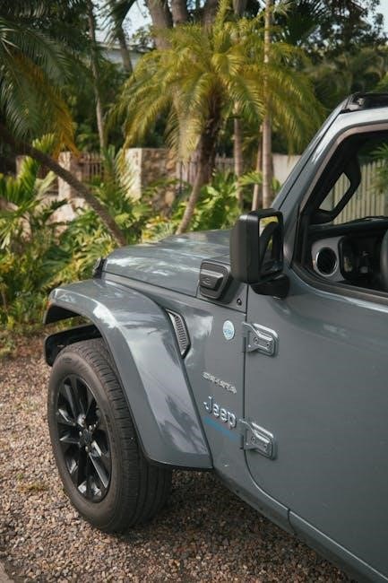
Welcome! This manual details the Jeep Grand Cherokee’s features, operation, and maintenance; disregard features not present on your specific vehicle model.

What This Manual Covers

This Jeep Grand Cherokee Owner’s Manual provides comprehensive information regarding your vehicle’s operation, maintenance, and safety features. It details everything from understanding dashboard symbols and controls to performing routine fluid checks and scheduled maintenance. You’ll find guidance on utilizing the Uconnect system, navigation, and audio controls, alongside explanations of driving modes like Quadra-Trac and Sele-Terrain.

Furthermore, this manual outlines emergency procedures, jump-starting instructions, and towing information. It also includes details about your vehicle’s warranty, including the basic vehicle and powertrain limited warranties, as well as the roadside assistance program. Remember to consult this manual for specifics related to your Grand Cherokee model year.

Important Safety Information

Safety is paramount! This Jeep Grand Cherokee is a specialized utility vehicle capable of advanced maneuvers; always operate it responsibly and within its intended capabilities. Familiarize yourself with the airbag system details and proper seating and safety restraint usage for all occupants.

Always heed all warning labels and follow recommended maintenance schedules. Ignoring safety precautions can lead to serious injury or vehicle damage. This manual highlights critical safety features, but it’s your responsibility to understand and utilize them correctly. Prioritize safe driving practices and be aware of your surroundings at all times.

Vehicle Identification

Locating your vehicle’s unique identifiers is crucial for service, warranty claims, and theft recovery. The Vehicle Identification Number (VIN) is a 17-character code providing specific details about your Jeep Grand Cherokee. You’ll find the VIN on the driver’s side dashboard, visible through the windshield, and on your vehicle’s registration and insurance documents.

Additionally, a Federal Emission Control Information label details compliance information. Understanding these identifiers ensures accurate parts ordering and proper servicing. Keep your VIN readily accessible for all interactions related to your vehicle; Refer to your owner’s manual for the precise location of these important markings.

Understanding Your Vehicle

Familiarize yourself with the Jeep Grand Cherokee’s components, controls, and systems detailed within this section for optimal driving and ownership experiences.

Dashboard Symbols and Indicators

Understanding the symbols illuminating on your Jeep Grand Cherokee’s dashboard is crucial for safe operation. This section provides a comprehensive guide to interpreting each indicator light, ranging from critical warnings requiring immediate attention – such as the check engine or oil pressure lights – to informational displays.

Pay close attention to symbols related to safety systems like airbags, anti-lock brakes (ABS), and the electronic stability control (ESC). Familiarize yourself with lights indicating system malfunctions, low fluid levels, or necessary maintenance. Ignoring warning lights can lead to vehicle damage or compromise safety. Refer to this manual for detailed explanations of each symbol and recommended actions when illuminated.

Instrument Panel Overview

The instrument panel of your Jeep Grand Cherokee provides vital information at a glance. Centrally located, the speedometer and tachometer display vehicle speed and engine RPM. Flanking these are fuel level and temperature gauges, ensuring optimal engine performance monitoring.

Digital displays present critical data like odometer readings, trip information, and selectable vehicle settings. Warning lights and indicator symbols alert you to system status and potential issues. The panel’s layout is designed for intuitive operation, allowing drivers to quickly assess vehicle conditions without distraction. Familiarize yourself with all components for a confident and informed driving experience.

Steering Wheel Controls

Your Jeep Grand Cherokee’s steering wheel integrates numerous controls for convenient operation while driving. Easily manage audio functions – volume, track selection, and source input – without taking your hands off the wheel. Cruise control settings are also readily accessible, promoting relaxed highway driving.

Additional controls allow for hands-free phone calls and voice command activation via the Uconnect system. Multi-function buttons provide access to vehicle information displayed in the instrument cluster. These intuitive controls enhance driver focus and safety, streamlining interaction with vehicle systems. Familiarize yourself with their placement and function for optimal control.

Seating and Safety Restraints

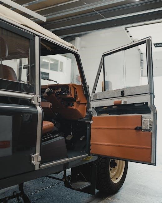
Proper seating and restraint usage are crucial for safety in your Jeep Grand Cherokee. This section details adjustments for both front and rear seats, ensuring optimal comfort and positioning. Learn how to correctly operate manual and power seat adjustments, including lumbar support and headrest settings.

Safety restraint systems, including three-point seatbelts and airbags, are designed to protect occupants during a collision. Understand the proper way to secure all passengers, including children, using appropriate restraints. Familiarize yourself with the airbag system details, including locations and deployment information, for maximum safety awareness.

Front Seat Adjustments

Optimizing your driving position is key for comfort and safety. Jeep Grand Cherokee front seats offer multiple adjustments. Manual seats utilize levers for fore/aft positioning, seatback angle, and height. Power seats incorporate switches for these functions, often including memory settings to store preferred positions.

Lumbar support adjustments cater to lower back comfort, while headrests should be positioned to support the back of your head. Correct adjustment ensures proper visibility and control. Regularly check and adjust these features to maintain an ideal driving posture, enhancing both comfort and safety during your journey.

Rear Seat Configurations

The Jeep Grand Cherokee offers versatile rear seating arrangements to maximize passenger comfort and cargo space. Many models feature 60/40 split-folding rear seats, allowing for various configurations. You can fold down one section for longer items while still accommodating passengers, or fold both sections flat to expand cargo capacity significantly.

Some trims include power-folding rear seats for added convenience. Release mechanisms are typically located on the seatbacks or in the cargo area. Ensure seats are securely latched when returned to the upright position. Understanding these configurations allows you to adapt the interior to your specific needs, whether transporting passengers or hauling gear.

Airbag System Details

The Jeep Grand Cherokee is equipped with an advanced airbag system designed to provide occupant protection in various collision scenarios. This system includes front airbags, side-curtain airbags, and often, seat-mounted side airbags. Airbags deploy rapidly, but are not guaranteed to deploy in all accidents.

Proper seating position and seatbelt use are crucial for airbag effectiveness. Never place rear-facing child seats in front of active airbags. The airbag system includes warning lights on the instrument panel to indicate system status. Regularly check for illuminated warnings and consult a qualified technician if issues arise. Understanding the system’s limitations and proper usage is vital for safety.

Operating Your Vehicle

Learn to safely start, drive, and utilize the Jeep Grand Cherokee’s diverse driving modes and systems for optimal performance and control.

Starting and Stopping the Engine

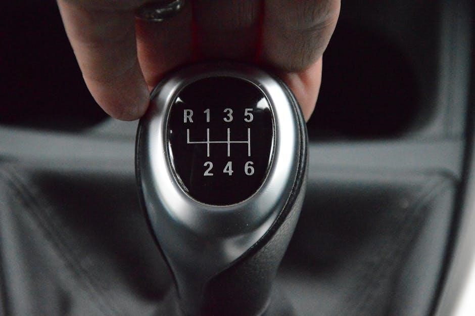
Starting your Jeep Grand Cherokee requires a fully depressed brake pedal and pressing the start/stop button. Ensure the gear selector is in Park or Neutral. The vehicle may briefly chime during startup – this is normal.

To stop the engine, simply press the start/stop button while the vehicle is in Park or Neutral. Do not turn the key, as this model utilizes a push-button start system. Allow the engine to fully cease operation before exiting the vehicle.

Important Note: Avoid prolonged idling, especially in extreme temperatures, to conserve fuel and minimize emissions. Familiarize yourself with the vehicle’s automatic start/stop function, if equipped, for enhanced fuel efficiency.

Driving Modes and Systems

The Jeep Grand Cherokee offers versatile driving experiences through advanced systems like Quadra-Trac I, II, and III. Quadra-Trac I provides full-time four-wheel drive, while II adds a two-speed transfer case for low-range capability. Quadra-Trac III further enhances off-road prowess with electronic limited-slip differentials.

Sele-Terrain allows drivers to customize on-road and off-road performance. Select from Auto, Sport, Snow, Sand/Mud, and Rock modes to optimize traction and handling for various conditions. These systems work in harmony to deliver exceptional control and capability, making the Grand Cherokee a truly adaptable vehicle.

Consult your vehicle’s specific configuration to understand which systems are equipped.

Quadra-Trac I/II/III Systems

Quadra-Trac I delivers seamless, full-time four-wheel drive, automatically adjusting torque for optimal traction. Quadra-Trac II builds upon this with a two-speed transfer case, enabling low-range gearing for challenging terrain and increased torque. This is ideal for steep inclines or deep snow.

Quadra-Trac III represents the pinnacle of Jeep 4×4 technology. It incorporates an electronic limited-slip rear differential, enhancing grip by distributing torque to the wheel with the most traction. This system provides superior control and stability in demanding off-road situations. Each system is designed to enhance the Grand Cherokee’s capability.

Sele-Terrain System

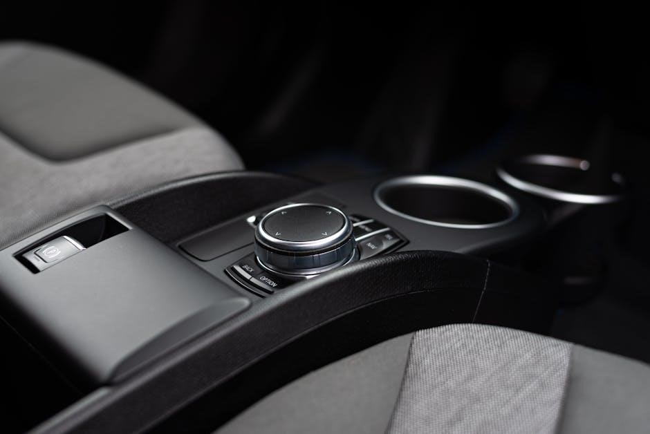
The Sele-Terrain System allows drivers to customize on-road and off-road performance. It offers selectable driving modes – Auto, Snow, Sand/Mud, Sport, and Rock – tailoring the vehicle’s systems for specific conditions.

Auto mode adapts to varying conditions. Snow provides increased traction on slippery surfaces. Sand/Mud optimizes for loose terrain. Sport enhances responsiveness. Rock delivers maximum articulation and control for extreme off-roading. This system adjusts several parameters, including engine torque, transmission shift points, and electronic stability control, to optimize performance and driver confidence.

Fueling and Fluid Checks

Fueling: Your Jeep Grand Cherokee requires unleaded gasoline with an octane rating of 87 or higher. Always ensure the fuel cap is securely tightened after refueling to prevent fuel vapor emissions.

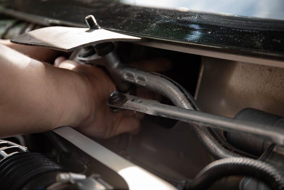
Fluid Checks: Regularly inspect engine oil, coolant, brake fluid, power steering fluid, and windshield washer fluid levels. Refer to the vehicle’s specifications for correct fluid types. Low fluid levels can impact performance and potentially cause damage. Checking these fluids is a crucial part of preventative maintenance, ensuring optimal vehicle operation and longevity. Consult the manual for specific locations and procedures for each fluid check.

Maintenance and Care

Regular maintenance is vital for your Jeep Grand Cherokee’s performance and longevity; follow the scheduled maintenance plan outlined within this owner’s manual.

Scheduled Maintenance

Maintaining your Jeep Grand Cherokee requires adherence to a specific maintenance schedule, ensuring optimal performance and reliability. This schedule, detailed within this owner’s manual, outlines necessary services at various mileage intervals.

These services include oil and filter changes, tire rotations, fluid level checks (coolant, brake, power steering, and transmission), and inspections of critical components like brakes, suspension, and exhaust systems. Following the recommended schedule helps prevent unexpected breakdowns and costly repairs.

Important: Keep detailed records of all maintenance performed, including dates, mileage, and services completed. This documentation is crucial for warranty claims and can enhance the vehicle’s resale value. Refer to the manual for specific intervals and recommended fluids.

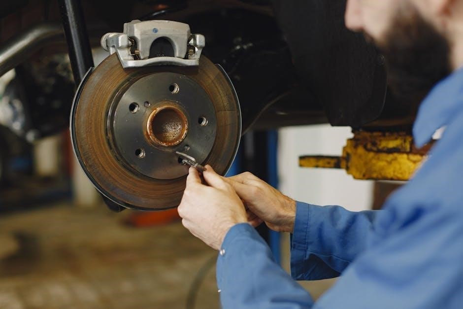
Tire Information and Maintenance

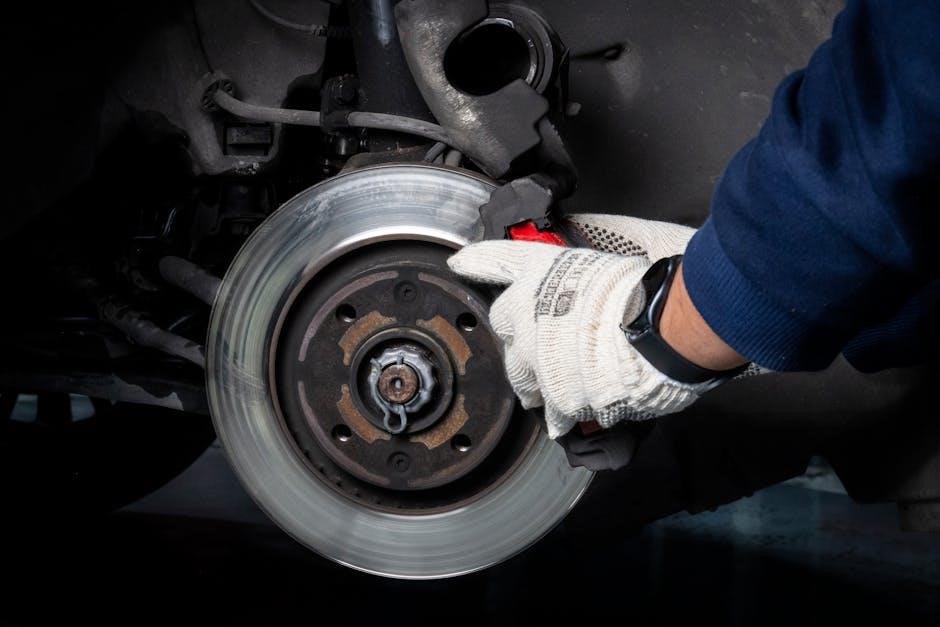
Proper tire care is vital for your Jeep Grand Cherokee’s safety and performance. This section details recommended tire pressures, found on the vehicle’s door jamb placard, not the tire sidewall. Maintaining correct pressure optimizes handling, fuel efficiency, and tire lifespan.

Regularly inspect tires for wear, damage (cuts, bulges), and uneven tread wear. Rotate tires according to the schedule in this owner’s manual to promote even wear. Check tread depth using a tread depth gauge; replace tires when they reach the minimum legal limit.

Remember: Use only tires of the correct size and load rating as specified in this manual. Incorrect tires can compromise vehicle stability and safety. Always balance tires when installed or rotated.

Fluid Specifications

Maintaining correct fluid levels with the specified types is crucial for your Jeep Grand Cherokee’s longevity. This section lists the recommended fluids for engine oil, coolant, transmission, brake fluid, power steering, and transfer case (if equipped).

Always refer to this owner’s manual for the exact fluid specifications (API/SAE grades, Chrysler Material Standards) as using incorrect fluids can cause damage. Regularly check fluid levels using the dipsticks or reservoir markings.

Features and Technology

Explore advanced systems! This section details the Jeep Grand Cherokee’s Uconnect, navigation, audio, and climate control features for an enhanced driving experience.

Uconnect System Overview

Uconnect is your Jeep Grand Cherokee’s integrated infotainment system, offering seamless connectivity and control. It features a user-friendly touchscreen interface for accessing audio, navigation, climate settings, and vehicle information.

Customize your experience with available features like Apple CarPlay and Android Auto integration, allowing smartphone mirroring for calls, messages, and app access. Stay connected on the go with available Wi-Fi hotspot capability.

The system also supports voice commands for hands-free operation, enhancing safety while driving. Explore Uconnect’s various menus and settings to personalize your driving experience and discover its full potential. Refer to the detailed Uconnect guide within this manual for comprehensive instructions and troubleshooting tips.

Navigation System Details

Your Jeep Grand Cherokee’s navigation system provides turn-by-turn directions, points of interest, and real-time traffic updates (subscription may be required). The system utilizes a high-resolution touchscreen display for easy map viewing and input.

Enter destinations by address, point of interest, or coordinates. Utilize voice guidance for hands-free navigation. The system automatically recalculates routes based on traffic conditions and detours.

Map updates are periodically available to ensure accuracy; check for updates through the Uconnect system or the Jeep website. Familiarize yourself with the system’s settings to customize preferences like route options and map display. Detailed instructions and troubleshooting are found within this manual.

Audio System Controls

The Jeep Grand Cherokee features a premium audio system controllable via the Uconnect touchscreen, steering wheel-mounted controls, and physical buttons. Adjust volume, tuning, and source selection (radio, USB, Bluetooth, etc.) easily.

Explore preset station memory for quick access to favorite radio stations. Bluetooth connectivity allows for wireless audio streaming from compatible smartphones and hands-free calling. Utilize the equalizer settings to customize the sound profile to your preference.

Detailed instructions on pairing devices, managing playlists, and accessing advanced audio features are provided within this manual. Explore the system’s capabilities for an enhanced driving experience.

Climate Control System

Your Jeep Grand Cherokee’s climate control system offers multi-zone temperature regulation for optimal comfort. Adjust temperature, fan speed, and airflow direction using the intuitive controls on the Uconnect touchscreen or physical buttons.

Activate the automatic temperature control for a set-and-forget experience, maintaining your desired cabin temperature. Utilize the defrost and defog functions for clear visibility in adverse weather conditions. Rear passengers may have independent climate controls, depending on the vehicle configuration.

Refer to this manual for detailed instructions on operating all climate control features, including recirculation mode and air quality settings.

Troubleshooting and Emergency Procedures

This section provides guidance for jump starting, towing, and handling emergency situations; always prioritize safety and follow detailed instructions carefully.

Jump Starting Procedures

Caution! Jump starting requires careful adherence to safety protocols to prevent damage to the vehicle’s electrical system and potential injury. Ensure both vehicles are turned off before connecting cables. Connect the positive (+) cable to the positive terminal of the discharged battery, then to the positive terminal of the boosting battery.

Next, connect the negative (-) cable to the negative terminal of the boosting battery, and finally, to a solid, unpainted metal surface on the disabled vehicle – not the negative battery terminal. Start the boosting vehicle and let it run for a few minutes. Attempt to start the disabled vehicle. If it doesn’t start immediately, wait a few more minutes and try again. Disconnect cables in the reverse order of connection.

Towing Information

Important! The Jeep Grand Cherokee is a specialized utility vehicle capable of certain towing tasks, but limitations exist. Refer to your vehicle’s specific towing capacity, found in this manual and on the vehicle’s door jamb sticker, before attempting to tow. Exceeding the maximum towing capacity can cause significant damage.

When towing, use appropriate towing equipment – a properly rated hitch, safety chains, and wiring harness. Ensure the trailer has functioning brakes and lights. Drive cautiously and allow for increased stopping distances. Regularly inspect the towing equipment for wear or damage. Improper towing can void your warranty.

What to Do in an Emergency

Stay Calm! This section outlines procedures for various emergency situations. In case of an accident, ensure the safety of yourself and passengers first. Activate hazard lights and assess injuries. If possible, move the vehicle to a safe location away from traffic.

For jump-starting procedures (see also dedicated section), follow the instructions carefully to avoid damage. If stranded, utilize the roadside assistance program detailed in the warranty information. Know your vehicle’s location for accurate assistance. Familiarize yourself with the location of the spare tire and jack. Always prioritize safety and call for professional help when needed.

Warranty Information

Coverage Details: Your Jeep includes a basic vehicle warranty, a powertrain limited warranty, and access to a comprehensive roadside assistance program for peace of mind.

Basic Vehicle Warranty

Comprehensive Coverage: The Basic Vehicle Warranty provides bumper-to-bumper coverage for defects in materials or workmanship. This warranty typically covers a specified period, such as 3 years or 36,000 miles (60,000 kilometers), whichever comes first. It protects against a wide range of issues, including component failures and manufacturing defects.

What’s Included: This warranty encompasses repairs needed to correct covered defects, including parts and labor. Certain exclusions apply, such as wear-and-tear items like brake pads and filters. Refer to your warranty booklet for a complete list of covered and excluded components. Maintaining your vehicle according to the scheduled maintenance program is crucial for warranty validity.

Claim Process: To make a warranty claim, contact your authorized Jeep dealership. They will diagnose the issue and determine if it’s covered under the Basic Vehicle Warranty.

Powertrain Limited Warranty

Engine & Transmission Protection: The Powertrain Limited Warranty focuses on the core components of your Jeep Grand Cherokee – the engine, transmission, and drivetrain. This warranty generally extends beyond the Basic Vehicle Warranty, often covering 5 years or 60,000 miles (100,000 kilometers). It provides peace of mind against major mechanical failures.

Covered Components: Specifically, this warranty typically includes the engine’s internal parts, transmission components, transaxle, driveshaft, rear axle, and related parts. Proper maintenance, as outlined in the owner’s manual, is essential to maintain warranty coverage.

Warranty Service: Should a covered component fail, authorized Jeep dealerships will perform the necessary repairs using genuine Jeep parts. Review your warranty booklet for detailed information regarding coverage specifics and claim procedures.

Roadside Assistance Program

24/7 Support: Your new Jeep Grand Cherokee comes with a comprehensive Roadside Assistance Program, offering 24 hours a day, 7 days a week support. This valuable service provides assistance if your vehicle is disabled due to a mechanical breakdown, accident, or other covered event.

Services Included: Common services include towing (to the nearest Jeep dealership), jump-start assistance, tire change service (with a good spare), fuel delivery (if out of gas), and lockout assistance. Coverage terms and limitations apply, so review your owner’s manual.

How to Access: To access Roadside Assistance, simply call the dedicated toll-free number provided in your owner’s manual or the Jeep app. Be prepared to provide your vehicle identification number (VIN) and location.

high pointe microwave oven manual

High Pointe Microwave Oven Manual: A Comprehensive Guide

This manual provides detailed instructions for High Pointe microwave models like EC028BMR and EC942KIW/EC942K9E, covering operation, troubleshooting, safety, and maintenance procedures.

Understanding Your High Pointe Microwave

Your High Pointe microwave oven is designed for efficient and convenient cooking, reheating, and defrosting. Familiarizing yourself with its features will ensure optimal performance and longevity. This appliance utilizes microwave energy to excite water molecules within food, generating heat. Understanding this principle is key to proper usage.

The control panel offers various functions, including speedy cooking via number keys (1-6), a clock function for timekeeping, and specific power levels for different food types. During operation, you can check the clock by pressing the ‘CLOCK’ button. Always use microwave-safe containers and avoid metal objects, as these can cause sparking and damage. Refer to the instruction manual for detailed guidance on each function and safety precaution. Proper operation guarantees safe and effective use of your High Pointe appliance.

Model Number Identification

Locating your High Pointe microwave’s model number is crucial for accessing the correct instruction manual, ordering replacement parts, and receiving accurate customer support. The model number is typically found on a sticker or plate affixed to the appliance. Common locations include the rear panel, inside the door frame, or on the side of the cabinet.

Frequently referenced model numbers include EC028BMR, EC942KIW, and EC942K9E. Ensure you accurately record the complete model number, as even slight variations can indicate different specifications. When contacting customer service or searching online for information, providing the correct model number will expedite the process and guarantee you receive the appropriate assistance for your specific High Pointe microwave oven. This ensures compatibility with parts and accurate troubleshooting guidance.

Locating the Instruction Manual

Finding your High Pointe microwave oven’s instruction manual is essential for safe and effective operation. Initially, check within the packaging that accompanied your appliance; a printed copy is often included. If you’ve misplaced the original, several online resources can assist you. Many websites archive manuals for various appliances, including High Pointe models like EC028BMR and EC942KIW/EC942K9E.

A targeted web search using your specific model number (e.g., “EC942K9E instruction manual”) will yield relevant results. Alternatively, the manufacturer’s website may host downloadable manuals. Remember to have your model number readily available when searching, as it ensures you download the correct manual for your High Pointe microwave. Accessing the manual provides vital safety information and operating instructions.

Common High Pointe Microwave Models

High Pointe offers a range of microwave oven models designed for various kitchen needs. Popular models frequently encountered include the EC028BMR, a standard countertop microwave, and the EC942KIW and EC942K9E, often featuring convection capabilities for enhanced cooking versatility. These models cater to diverse user preferences, from basic reheating to more complex culinary tasks.

Understanding your specific model number is crucial when seeking support, replacement parts, or accessing the correct instruction manual. Each model may have unique features and operating procedures. The EC942K9E, for instance, requires specific attention when locating the fuse. Identifying your High Pointe microwave’s model ensures you receive accurate guidance and maintain optimal performance.

EC028BMR

The High Pointe EC028BMR is a commonly used countertop microwave oven, known for its straightforward functionality. This model provides essential cooking features, including various power levels and timer settings, suitable for everyday heating and basic cooking tasks. Users can quickly initiate cooking by pressing number keys from 1 to 6 for speedy cooking options, offering convenience for frequently used cooking times.

During operation, pressing the CLOCK button allows users to check the current time without interrupting the cooking process. This model’s simplicity makes it user-friendly, though referencing the full instruction manual is recommended for optimal use and safety precautions. Proper container usage is vital for safe and efficient operation with the EC028BMR.

EC942KIW & EC942K9E

The High Pointe EC942KIW and EC942K9E microwave oven models share similar features and operational guidelines, detailed within their respective instruction manuals. These models often include convection capabilities alongside standard microwave functions, offering versatile cooking options. Locating the model number is crucial for accessing specific support and troubleshooting information.

A common concern with these models involves identifying the fuse location, particularly in the EC942K9E. Users should consult the manual for precise instructions. Like the EC028BMR, these models allow users to check the clock during cooking by pressing the CLOCK button. Speedy cooking is initiated using the number keys (1-6). Always prioritize safety guidelines and proper container usage.

Operating Instructions

High Pointe microwave ovens offer basic cooking functions and speedy cooking via number key usage (1-6). Users can easily check the clock during operation.

Basic Cooking Functions

High Pointe microwaves are designed for simple and efficient cooking. To begin, ensure the microwave door is securely closed. Input the desired cooking time using the number pad; for example, pressing ‘3’ initiates three minutes of cooking at a standard power level. The power level can often be adjusted using dedicated buttons, allowing for defrosting, reheating, or full-power cooking.

Many models feature pre-programmed settings for common foods like popcorn, potatoes, or frozen dinners. These settings automatically adjust the cooking time and power level for optimal results. Always refer to food packaging instructions as a guide, and monitor the cooking process to prevent overcooking. Remember to use microwave-safe containers and cover food to retain moisture and prevent splattering. After setting the time and power, press the ‘Start’ button to begin cooking.

Speedy Cooking – Number Key Usage (1-6)

High Pointe microwaves offer a convenient “Speedy Cooking” feature utilizing the number keys 1 through 6 for quick cooking times. Pressing a number key directly corresponds to a pre-set cooking duration, eliminating the need to input minutes and seconds manually. Typically, ‘1’ equates to one minute, ‘2’ to two minutes, and so on, up to ‘6’ for six minutes of cooking.

This function is ideal for rapidly reheating small portions or quickly cooking frequently used items. The power level during speedy cooking is usually set to high, but some models allow adjustment before initiating the cycle. Always ensure food is appropriately covered to prevent splattering. This method streamlines the cooking process, offering a fast and efficient way to utilize your High Pointe microwave.

Checking the Clock During Cooking

While your High Pointe microwave is actively cooking, you can easily check the current time without interrupting the cooking process. Simply press the “CLOCK” button once during any cooking cycle. The display will momentarily pause the cooking timer and show the current time. This allows you to monitor how much time remains or simply verify the time of day without affecting the ongoing operation.

After a brief display of the time, the microwave will automatically resume the cooking cycle from where it left off. This feature is particularly useful for ensuring accurate cooking times and maintaining awareness of the overall cooking duration. Remember to avoid repeatedly pressing the “CLOCK” button, as it might disrupt the cooking cycle.

Using the Clock Function

The clock function on your High Pointe microwave allows you to set and maintain the correct time, essential for accurate cooking and utilizing timed features. To set the clock, initially press the “CLOCK” button. The display will likely show a flashing time, indicating it’s ready for input. Use the number keys (1-6) to enter the desired hour and minute.

After entering the time, press the “CLOCK” button again to confirm your settings. The microwave will then display the current time continuously, even when not in use. This ensures the clock remains synchronized for future cooking operations. Regularly checking and adjusting the clock guarantees precise timing for all your microwave recipes and functions.

Troubleshooting Common Issues

This section details solutions for problems like the microwave not working, sparking, or fuse issues (EC942K9E), offering a problem & solution chart.

Microwave Not Working

If your High Pointe microwave isn’t operating, begin by verifying the power supply. Ensure the appliance is securely plugged into a functioning electrical outlet. A simple reset can often resolve minor glitches; unplug the microwave for a few minutes, then plug it back in.

Next, check the door to confirm it’s closing and latching correctly. The microwave won’t function if the door isn’t securely closed, as a safety interlock prevents operation. Inspect the fuse, particularly for models like the EC942K9E, as a blown fuse is a common cause of complete failure.

If these steps don’t restore power, consult the problem & solution chart for further diagnostics. If the issue persists after these checks, contacting customer support or a qualified technician is recommended to avoid potential hazards and ensure proper repair.

Sparking Inside the Cavity

Sparking within your High Pointe microwave typically indicates an issue with the items inside or the microwave’s interior. Immediately stop the microwave and disconnect it from the power source. The most frequent cause is using metal containers, utensils, or dishes with metallic trim. These materials reflect microwaves, causing arcing and sparking.

Carefully inspect the cavity for any metal objects, including foil, twist ties, or even damaged cookware. Ensure the waveguide cover (often a mica sheet) isn’t damaged or excessively dirty, as this can also lead to sparking. A damaged waveguide cover must be replaced.

If no metal is present and the waveguide cover is intact, the sparking might indicate a more serious internal problem. In such cases, do not attempt self-repair; contact qualified service personnel for inspection and repair.

Metal Objects & Trim

Using metal in your High Pointe microwave is a significant safety hazard and a common cause of sparking and potential damage. Never operate the microwave with any metal objects inside, including cookware, utensils, aluminum foil, or metal-edged dishes. Even small amounts of metallic trim on ceramics or glassware can cause arcing.

Microwaves reflect off metal surfaces, creating electrical currents that can ignite fires or damage the microwave’s internal components. This includes seemingly harmless items like disposable aluminum pie plates or twist ties securing food packaging.

Always ensure all containers and utensils are microwave-safe before use. Glass, ceramic, and plastic specifically labeled for microwave use are generally safe. Regularly inspect your cookware for hidden metal components or damage. Prioritize safety and avoid any risk of metal exposure within the microwave cavity.

Fuse Location (EC942K9E)

For the High Pointe EC942K9E model, locating and replacing the fuse is a crucial step in resolving certain operational issues. Before attempting any repairs, always disconnect the microwave from the power outlet to prevent electrical shock. The fuse is typically located within the microwave’s control panel assembly, accessible from the rear of the unit.

To access the fuse, you’ll likely need to remove the outer casing of the microwave. This usually involves unscrewing several screws located on the back and sides. Once the casing is removed, carefully locate the fuse holder within the control panel area.

The fuse is a small glass tube containing a wire filament. Inspect the filament; if it’s broken or blackened, the fuse is blown and needs replacement. Use a fuse with the exact same amperage and voltage rating to ensure safe operation. Reassemble the microwave carefully after replacement.

Problem & Solution Chart

Encountering issues with your High Pointe microwave? This chart offers quick solutions to common problems. Microwave not heating? Check the power cord, ensure the door closes securely, and verify cooking time/power level settings. Sparking inside? Immediately stop the microwave and inspect for metal objects or damaged waveguide cover. Never operate with a damaged cover!

If the turntable isn’t rotating, ensure it’s properly seated on the drive and the drive is clean. For a non-responsive control panel, try resetting the microwave by unplugging it for a few minutes. If the fuse is blown (EC942K9E model), replace it with the correct amperage.

Persistent issues? Contact company support for assistance. Remember safety first – always disconnect power before inspecting or attempting repairs. This chart provides basic troubleshooting; complex problems may require professional service.

Safety Precautions

Always use microwave-safe containers and avoid metal objects, including trim, to prevent sparking. Follow general safety guidelines for safe operation and maintenance.

Proper Container Usage

When utilizing your High Pointe microwave oven, selecting appropriate containers is crucial for both safety and optimal cooking results. Always ensure that any dishware or utensil placed inside is explicitly labeled as “microwave-safe;” Materials like certain plastics, glass, and ceramics are generally suitable, but always verify the manufacturer’s instructions.

Avoid using containers with metallic trim, as these can cause sparking and potential damage to the microwave. Metal cookware, aluminum foil, and twist ties are strictly prohibited inside the microwave cavity. Paper plates and cups should be used cautiously, as they can sometimes overheat and ignite.

For best results, use shallow, rectangular or oval-shaped dishes, as they promote more even heating. Covering food with a microwave-safe lid or vented plastic wrap helps retain moisture and prevent splattering. Regularly inspect your containers for cracks or chips, and discard any damaged items immediately.

Avoiding Metal Objects

The presence of metal objects inside your High Pointe microwave oven poses a significant safety hazard and can lead to damage. Metal reflects microwaves, causing arcing, sparking, and potentially a fire. This includes aluminum foil, metal cookware, silverware, and even dishes with metallic trim or accents.

Never operate the microwave if any metal object is present within the cavity. Even small items like twist ties, staples, or metal-reinforced plastic can cause problems. Be particularly cautious with takeout containers, as some may contain hidden metal components.

If sparking occurs, immediately press the “Stop” or “Cancel” button and disconnect the power supply. Thoroughly inspect the microwave interior to identify and remove any metallic source. Ignoring this precaution can result in permanent damage to the magnetron and other internal components, voiding your warranty.

General Safety Guidelines

To ensure safe operation of your High Pointe microwave oven, always supervise children when the appliance is in use. Never attempt to operate the microwave with a damaged cord or plug, or if it has been dropped or subjected to impact. Repairs should only be performed by qualified service personnel.

Avoid heating sealed containers, as pressure buildup can cause them to explode. Pierce foods with skins, like potatoes or sausages, before microwaving to prevent bursting. Use caution when removing heated food, as containers and contents may be very hot.

Regularly inspect the door seals and the interior for damage. Do not use the microwave if the door does not close securely. Never tamper with the safety interlocks; Following these guidelines will help prevent accidents and maintain the longevity of your appliance.

Maintenance & Care

Regular cleaning of both the interior and exterior surfaces is crucial for optimal performance and longevity of your High Pointe microwave oven.

Cleaning the Interior

To maintain a clean and efficient cooking environment within your High Pointe microwave, regular interior cleaning is essential. Begin by unplugging the appliance to ensure safety. Then, carefully remove the turntable and roller ring, washing them in warm, soapy water. For stubborn food splatters or stains inside the cavity, a simple solution of water and lemon juice can be incredibly effective.

Place the mixture in a microwave-safe bowl and heat on high for several minutes, allowing the steam to loosen debris. Afterwards, wipe down the interior surfaces with a soft cloth or sponge. Avoid abrasive cleaners or scouring pads, as these can damage the interior lining. Pay particular attention to the top, sides, and door of the microwave. Rinse thoroughly with a damp cloth and dry completely before reassembling the turntable and resuming operation. Consistent cleaning prevents odors and ensures optimal cooking performance.

Cleaning the Exterior

Maintaining the exterior of your High Pointe microwave oven is crucial for both aesthetics and longevity. Always begin by disconnecting the appliance from the power source before cleaning. Use a mild detergent mixed with warm water and a soft cloth to gently wipe down the exterior surfaces. Avoid harsh chemicals, abrasive cleaners, or scouring pads, as these can scratch or discolor the finish.

Pay close attention to the control panel and door handle, as these areas tend to accumulate fingerprints and grime. For stubborn stains, a slightly damp cloth may be necessary, but ensure no water enters the internal components. After cleaning, thoroughly dry the exterior with a clean, dry cloth to prevent water spots. Regular exterior cleaning will keep your High Pointe microwave looking its best and functioning optimally for years to come.

Regular Maintenance Checks

To ensure optimal performance and longevity of your High Pointe microwave oven, implement routine maintenance checks. Regularly inspect the door seals for any damage or debris, ensuring a tight closure for efficient cooking. Check the interior walls for food splatters or residue, cleaning them promptly to prevent buildup and odors; Verify the proper functioning of the turntable, ensuring smooth rotation during operation.

Periodically examine the exterior for any signs of damage or wear. If you notice sparking inside the cavity, immediately discontinue use and consult the troubleshooting section of this manual. Consistent attention to these details will help maintain your High Pointe microwave in excellent condition, preventing potential issues and extending its lifespan. Remember safety first – always disconnect power before inspection!

Parts & Support

For assistance, contact the company directly for support, replacement parts, or to inquire about Buy And Try Insurance options for your High Pointe oven.

Company Contact Information

Unfortunately, specific, readily available contact information for High Pointe microwave ovens is proving difficult to locate directly from the provided snippets. Many searches lead to requests for the model number to assist further, indicating a potentially fragmented support system. However, given the age of some references (dating back to 2018 and earlier), direct manufacturer support may be limited.

If you require assistance, it’s recommended to begin by thoroughly reviewing the instruction manual for your specific model (EC028BMR, EC942KIW, or EC942K9E). If the manual doesn’t resolve your issue, searching online appliance repair forums or contacting general appliance repair services in your area might yield helpful results. Retailers who previously sold High Pointe microwaves may also have contact information or be able to direct you to appropriate resources. Keep your model number handy when seeking support, as it’s crucial for identifying compatible parts and troubleshooting steps.

Finding Replacement Parts

Locating replacement parts for High Pointe microwaves can be challenging due to the brand’s potentially limited current manufacturing and support. The provided information suggests “Buy And Try Insurance Options” were once available, hinting at a past focus on parts accessibility, but current availability isn’t explicitly stated.

Your best approach involves identifying the precise model number (EC028BMR, EC942KIW, or EC942K9E) and then searching online appliance parts retailers. Websites specializing in microwave components are a good starting point. Be prepared to provide detailed specifications when ordering. Alternatively, local appliance repair shops may be able to source parts or offer compatible alternatives. Due to the age of some models, parts may be discontinued, requiring resourceful searching or considering repair options from qualified technicians. Always prioritize safety when handling appliance repairs.

Buy And Try Insurance Options

Historically, High Pointe offered “Buy And Try Insurance” as a consumer protection measure alongside their microwave ovens. Details regarding this insurance are scarce, but its existence suggests a commitment to customer satisfaction and a willingness to address potential product issues post-purchase. The insurance likely covered repairs or replacements within a specified timeframe, offering peace of mind to buyers.

However, current availability of this insurance is uncertain. The provided search snippets do not indicate whether the “Buy And Try Insurance” program is still active. Consumers should investigate directly with retailers or through any archived documentation accompanying their specific High Pointe microwave model. If unavailable, standard manufacturer warranties or extended protection plans offered by retailers may provide comparable coverage. Always review the terms and conditions carefully before purchasing any insurance or warranty.

dbxr463ed1ww repair manual

DBXR463ED1WW Repair Manual: An Overview

This comprehensive DBXR463ED1WW General Electric Dryer repair manual offers sections, parts lists, and care guides, alongside community forums for troubleshooting assistance.

The General Electric DBXR463ED1WW dryer is a standard household appliance designed for efficient clothes drying. This introduction to the repair manual aims to equip users with the necessary knowledge to diagnose and resolve common issues. Understanding the dryer’s core functions – heating, tumbling, and ventilation – is crucial for effective repair.

Before attempting any repairs, always prioritize safety by disconnecting the power supply. This manual provides detailed guidance on identifying key components, navigating electrical and mechanical systems, and utilizing calculators for precise measurements. Accessing official repair manuals and sourcing replacement parts are also covered, ensuring a smooth and successful repair process. Remember to consult parts diagrams for accurate identification.

Safety Precautions Before Repair

Crucially, before commencing any repair work on the DBXR463ED1WW dryer, always disconnect the appliance from the power supply. This prevents electric shock and ensures personal safety. Wear appropriate safety gear, including insulated gloves and eye protection.

Gas dryers require additional caution; shut off the gas supply valve. Be mindful of sharp edges on internal components. Never attempt repairs while fatigued or under the influence of medication. If unsure about any procedure, consult a qualified technician. Proper grounding is essential. Disconnect the dryer from both power and gas before disassembling any parts. Ignoring these precautions can lead to serious injury or damage.

Understanding Dryer Components

Dissecting the DBXR463ED1WW involves recognizing its electrical and mechanical systems, key parts, and how they interact to deliver efficient drying performance.

Identifying Key Parts of the DBXR463ED1WW

Successfully repairing the DBXR463ED1WW dryer necessitates a firm grasp of its core components. These include the heating element, responsible for generating heat; the drive belt, which facilitates drum rotation; and the motor, powering the entire tumbling process. The control panel governs dryer functions, while the thermal fuse acts as a safety mechanism, preventing overheating.

Further essential parts are the drum rollers supporting the drum’s movement, the lint filter maintaining airflow, and various sensors monitoring temperature and moisture levels. Understanding the function and location of each part is crucial for accurate diagnosis and effective repair. Detailed parts diagrams, readily available online, are invaluable resources for identification during disassembly and reassembly.

Electrical System Breakdown

The DBXR463ED1WW dryer’s electrical system is a complex network powering its functions. It begins with the power cord supplying electricity to the control board, the system’s central command. From there, power distributes to the heating element, activating heat production, and the drive motor, initiating drum rotation. Safety components like the thermal fuse and thermostats protect against overheating and electrical faults.

A crucial element is the timer, controlling cycle duration. Wiring harnesses connect these components, and proper continuity is vital for operation. Troubleshooting requires a multimeter to check voltage, resistance, and continuity. Always disconnect power before inspecting electrical parts, prioritizing safety during any repair attempt.

Mechanical System Breakdown

The DBXR463ED1WW dryer’s mechanical system relies on several key components working in harmony. The drum, supported by rollers, allows clothes to tumble freely. A drive belt connects the motor to the drum, transferring rotational force. Tensioning pulleys maintain belt tightness, ensuring efficient operation. The blower wheel circulates air through the dryer, removing moisture.

Lint is captured by a lint filter, preventing blockage of the exhaust vent. Proper airflow is crucial for preventing overheating and fire hazards. Inspecting rollers, the belt, and the blower for wear and tear is essential during maintenance. A malfunctioning component can lead to noisy operation or complete system failure.

Common Issues and Troubleshooting

Typical problems with the DBXR463ED1WW include failure to start, lack of heat, a drum that won’t tumble, or excessive operational noises.

Dryer Not Starting: Possible Causes

Several factors can prevent your DBXR463ED1WW dryer from starting. First, verify the power supply – ensure the dryer is properly plugged into a functioning outlet and the circuit breaker hasn’t tripped. A blown thermal fuse is a common culprit, interrupting the electrical circuit. Inspect the door switch assembly; if faulty, it won’t signal the dryer to begin operation.

The drive belt could be broken or slipped off the motor pulley, preventing drum rotation and triggering a safety shut-off. A malfunctioning timer or electronic control board can also halt the start-up sequence. Finally, a faulty start switch may be the issue. Thoroughly check each component using a multimeter to diagnose the precise cause and restore functionality to your dryer.

Dryer Not Heating: Diagnostic Steps

If your DBXR463ED1WW dryer isn’t heating, begin by checking the gas supply (for gas dryers) or the electrical connection to the heating element (for electric models). A burned-out heating element is a frequent cause; test it for continuity with a multimeter. Inspect the thermal fuse and high-limit thermostat – these safety devices interrupt power if overheating is detected.

A faulty gas valve (gas dryers) or igniter can prevent ignition. For electric dryers, examine the control board for proper voltage output to the heating element. Also, verify the operation of the cycling thermostat, which regulates temperature. Carefully test each component to pinpoint the source of the heating failure and restore warm, dry clothes.

Drum Not Tumbling: Repair Solutions

A DBXR463ED1WW dryer drum failing to tumble often indicates a broken drive belt. Inspect the belt for wear, cracks, or breakage; replacement is straightforward. Check the drum rollers and glides – worn or damaged rollers create friction, hindering movement. Ensure the motor is functioning correctly; a faulty motor won’t rotate the drum.

Examine the idler pulley, which maintains belt tension; a seized pulley prevents tumbling. Also, verify that no clothing items are obstructing the drum’s rotation. Carefully assess each component, replacing worn parts and ensuring proper alignment to restore smooth drum operation and efficient drying performance.

Excessive Noise During Operation

Unusual noises from your DBXR463ED1WW dryer often signal mechanical issues. A squealing sound frequently points to a worn drive belt or idler pulley, requiring inspection and potential replacement. Grinding noises may indicate failing drum rollers or a damaged drum support. Check for obstructions like coins or buttons lodged within the blower housing or drum.

A rattling sound could stem from loose cabinet panels or internal components. Carefully examine the motor for unusual vibrations or bearing noise. Addressing these issues promptly prevents further damage and restores quiet, efficient dryer operation. Always disconnect power before inspecting internal parts.

Repair Procedures

Detailed step-by-step instructions guide you through replacing the heating element, drive belt, motor, and control panel on your DBXR463ED1WW dryer.

Replacing the Heating Element

Safety First: Disconnect power before starting! Access the heating element by removing the dryer’s access panels – typically rear or front. Carefully disconnect the wiring connected to the old heating element, noting its configuration for reassembly.

Remove the old element, often secured with screws or clips. Before installing the new heating element, inspect the element housing for any damage or debris. Install the new heating element, ensuring secure connections and proper alignment. Reconnect the wiring, mirroring the original setup.

Finally, reassemble the access panels and test the dryer to confirm proper heating function. A multimeter can verify element continuity before installation, ensuring a functional replacement.

Replacing the Drive Belt

Safety First: Disconnect the dryer from the power source! Access the drive belt usually requires removing the front panel and potentially the drum. Carefully note the belt’s routing around the motor pulley and drum. Release tension on the belt tensioner to remove the old belt.

Inspect the motor pulley and drum for wear or damage before installing the new belt. Install the new belt, ensuring it’s correctly seated in the drum and around the motor pulley. Re-engage the belt tensioner, verifying proper belt tension.

Reassemble the dryer, and test its operation to confirm the drum is tumbling correctly.

Replacing the Motor

Crucially, disconnect power before beginning! Accessing the motor typically involves removing the dryer’s cabinet and front panel, and potentially the blower housing. Disconnect the electrical connections and any retaining brackets securing the motor.

Carefully note the wiring configuration before disconnecting. Remove the old motor, and inspect the surrounding components for damage. Install the new motor, ensuring it’s securely mounted and all connections are properly reattached, matching the original wiring.

Test the dryer’s operation thoroughly after reassembly, verifying proper drum rotation and airflow.

Repairing the Control Panel

Always disconnect power before attempting control panel repairs! Begin by carefully removing the control panel assembly, noting the location of all wires and connectors. Inspect the panel for visible damage, such as burnt components or loose connections.

Testing individual components, like switches and relays, with a multimeter can pinpoint failures. Replacement of faulty components often requires soldering skills. Ensure proper grounding when reinstalling the panel.

Thoroughly test all functions after reassembly – cycle selection, temperature settings, and start/stop operation – to confirm successful repair.

Using a Calculator for Repair Calculations

From basic arithmetic for part costs to scientific functions for electrical resistance, a calculator is essential for accurate DBXR463ED1WW dryer repairs.

Basic Calculator Functions for Dryer Repair

When tackling DBXR463ED1WW dryer repairs, a foundational understanding of basic calculator functions proves invaluable. Addition and subtraction are crucial for calculating total part costs or determining dimensional differences during component replacement. Multiplication and division assist in converting units – for example, calculating wire lengths or resistance values based on specifications.

The percentage function is useful for determining voltage drops or efficiency losses. Square root calculations may be needed when dealing with circular components or areas. Don’t overlook the memory functions (M+, M-, MR, MC) for storing and recalling important values like original resistance readings or part numbers. A reliable online calculator with these functions streamlines the repair process, ensuring accuracy and efficiency.

Scientific Calculator Applications

Advanced DBXR463ED1WW dryer repairs often necessitate a scientific calculator’s capabilities. Trigonometric functions (sine, cosine, tangent) become relevant when analyzing angles in motor windings or belt alignments. Logarithmic functions aid in understanding decibel levels related to noise diagnostics. Exponential functions are useful for calculating power dissipation in heating elements or motor components.

Furthermore, scientific notation simplifies working with very large or very small resistance, capacitance, or inductance values. Unit conversions are essential for ensuring compatibility between metric and imperial measurements. Utilizing a scientific calculator with a math expression renderer and plotting features can significantly enhance complex calculations and problem-solving during intricate dryer repairs.

Online Calculator Resources

Numerous online calculators streamline DBXR463ED1WW dryer repair calculations. For basic arithmetic – voltage drops, current calculations – standard online calculators suffice. However, for more complex tasks, specialized resources prove invaluable; Free online scientific notation calculators handle the large and small values common in electrical components. Unit converters facilitate seamless transitions between measurement systems.

Websites offering math expression rendering and plotting tools aid in visualizing electrical circuits or mechanical stresses. Several platforms provide dedicated calculators for Ohm’s Law, power calculations, and even conversions between AC and DC voltages, proving essential for accurate diagnostics and repair work on your dryer.

Finding Manuals and Parts

Locate official DBXR463ED1WW repair manuals and source replacement parts through dedicated websites, utilizing parts diagrams for accurate identification and ordering.

Locating Official Repair Manuals

Finding the correct repair manual for your DBXR463ED1WW dryer is crucial for successful repairs. Begin your search on the official GE Support Website, as they often provide downloadable manuals in PDF format. These manuals contain detailed diagrams, troubleshooting guides, and parts lists specifically tailored to your model.

Alternatively, explore online resources dedicated to appliance repair manuals. Several websites specialize in archiving and selling service manuals for various appliances, including GE dryers. Be sure to verify the manual’s compatibility with the DBXR463ED1WW model number before purchasing.

Checking online repair forums and communities can also yield valuable leads. Experienced users frequently share links to manuals or offer guidance on where to find them. Remember to prioritize official sources whenever possible to ensure accuracy and safety.

Sourcing Replacement Parts for DBXR463ED1WW

Obtaining genuine replacement parts is vital when repairing your DBXR463ED1WW dryer. Start by visiting the official GE Parts website; they offer a comprehensive catalog searchable by model number. Numerous online appliance parts retailers also specialize in GE dryer components, providing competitive pricing and shipping options.

When ordering, always double-check the part number against your dryer’s parts diagram (found in the repair manual) to ensure compatibility. Understanding parts diagrams is essential for accurate identification. Consider local appliance repair shops; they may stock common parts or can order them for you.

Beware of counterfeit parts; purchase from reputable suppliers to guarantee quality and performance.

Understanding Parts Diagrams

DBXR463ED1WW dryer parts diagrams are essential for successful repairs, visually illustrating component locations and relationships. These diagrams, typically found within the repair manual or on the GE Parts website, use exploded views to showcase how parts assemble. Each part is labeled with a corresponding reference number and part number, crucial for ordering replacements.

Familiarize yourself with the diagram’s key; it explains symbols and abbreviations. Trace the connections between parts to understand their function within the system. Diagrams aid in disassembly and reassembly, preventing errors.

Online resources often offer interactive diagrams, allowing you to click on parts for detailed information.

Microsoft (MSFT) PE Ratio Analysis (Related Data)

As of February 5, 2026, Microsoft’s (MSFT) PE ratio is 24.62, a significant improvement from its 12-month average of 34.02.

Current PE Ratio of MSFT

Currently, as of February 7, 2026, Microsoft (MSFT) exhibits a Price-to-Earnings (PE) ratio of 24.62. This figure represents a notable decrease compared to its historical averages, positioning it as the lowest among the “Magnificent Seven” stocks. Over the past five years, MSFT has typically traded at a PE ratio around 33.4, indicating a potential undervaluation at its present level.

The PE ratio is a crucial valuation metric, reflecting the market’s assessment of a company’s earnings. A lower PE ratio can suggest that a stock is undervalued relative to its earnings, potentially offering an attractive investment opportunity. However, it’s essential to consider industry-specific benchmarks and future growth prospects when interpreting PE ratios.

Historical PE Ratio Trends

Analyzing Microsoft’s (MSFT) historical PE ratio reveals significant fluctuations. As of February 5, 2026, the PE ratio stood at 24.62, a substantial improvement from its 12-month average of 34.02, representing a -27.63% change. Data from October 29, 2025, shows consistent tracking of this key financial indicator.

These trends suggest periods of both market optimism and caution regarding MSFT’s future earnings potential. Investors closely monitor these shifts to gauge the stock’s valuation and potential for growth. Understanding these historical patterns provides valuable context for assessing current market conditions and making informed investment decisions regarding MSFT.

Forward PE Ratio Considerations

Microsoft’s (MSFT) forward PE ratio, currently at 30.49, offers a glimpse into future earnings expectations. This metric is crucial as it reflects investor sentiment regarding the company’s projected profitability. Compared to its five-year average of approximately 33.4, the current forward PE suggests a potentially more tempered outlook.

However, it’s essential to consider that forward PE ratios are based on estimates and can be influenced by various factors, including economic conditions and company-specific developments. A lower forward PE, like MSFT’s, might indicate undervaluation or concerns about future growth, requiring careful analysis alongside other financial indicators.

Additional Resources

Explore online repair forums and the official GE Support Website for valuable troubleshooting tips, community insights, and direct assistance with your DBXR463ED1WW dryer.

Online Repair Forums and Communities

Engaging with online repair forums and communities dedicated to appliance repair provides a wealth of knowledge and support for tackling DBXR463ED1WW dryer issues. These platforms host experienced DIYers and technicians willing to share their expertise, offering step-by-step guidance and solutions to common problems.

Users frequently post detailed descriptions of their repair experiences, including photos and videos, which can be invaluable when diagnosing and fixing your dryer. Searching existing threads can often reveal solutions to problems identical to yours, saving you time and effort. Active participation allows you to ask specific questions and receive personalized advice from knowledgeable individuals. Remember to always prioritize safety and consult official repair manuals when performing any repairs.

GE Support Website

The official GE Support website is an essential resource for DBXR463ED1WW dryer owners seeking repair information and assistance. It provides access to a comprehensive library of resources, including downloadable manuals, parts diagrams, and troubleshooting guides specifically tailored to your model.

You can often find frequently asked questions (FAQs) addressing common issues, as well as video tutorials demonstrating repair procedures. GE’s website also offers a parts ordering service, allowing you to directly purchase replacement components. Furthermore, it provides contact information for GE’s customer support team, enabling you to reach out for personalized assistance if needed. Utilizing these resources can significantly streamline your repair process.

stihl service manual pdf

Understanding Stihl Service Manuals: A Comprehensive Guide

Stihl service manuals, often available as a convenient PDF, are essential resources for owners and technicians alike. These detailed guides provide comprehensive instructions
for maintaining, troubleshooting, and repairing Stihl power equipment, ensuring optimal performance and longevity of your valuable tools.

Accessing a Stihl service manual PDF unlocks a wealth of technical information, empowering users to confidently address mechanical issues and perform routine maintenance tasks.

What is a Stihl Service Manual?

A Stihl service manual is a technically detailed guide created by Stihl specifically for servicing their range of power equipment. Typically available as a PDF download, these manuals are far more comprehensive than the owner’s manuals provided with new machines.

They contain in-depth information covering complete disassembly and reassembly procedures, detailed specifications, troubleshooting guides, exploded views of parts, and precise torque settings. A Stihl service manual PDF isn’t just for professional mechanics; it empowers informed DIY enthusiasts to perform complex repairs and maintenance tasks themselves.

These manuals are crucial for understanding the inner workings of Stihl products, ensuring correct repair procedures are followed, and maintaining the equipment to factory standards. Utilizing a genuine Stihl service manual guarantees access to accurate and reliable information, vital for safe and effective servicing.

Why Use a Stihl Service Manual PDF?

Utilizing a Stihl service manual PDF offers numerous advantages over relying solely on general repair guides or online videos. The PDF format provides instant access to a wealth of detailed information, readily available on your computer, tablet, or smartphone – eliminating the need for bulky physical manuals.

These manuals ensure accurate repairs by providing specific instructions, torque specifications, and exploded diagrams tailored to your exact Stihl model. Access to a PDF allows for easy printing of specific sections, or searching for particular components or procedures.

Furthermore, a Stihl service manual PDF promotes safety by guiding users through proper disassembly and reassembly, reducing the risk of damage or injury. It’s an invaluable resource for both professional technicians and dedicated homeowners seeking to maintain their Stihl equipment effectively.

Locating and Downloading Stihl Service Manuals

Stihl service manuals in PDF format are readily accessible through the official Stihl website and various third-party platforms, offering convenient download options.

Official Stihl Website for Manuals

Stihl’s official website serves as the primary and most reliable source for obtaining authentic service manuals in PDF format. Navigating to the Stihl website allows users to directly download manuals tailored to specific product models, ensuring accuracy and compatibility.

The website typically categorizes manuals by equipment type – chainsaws, blowers, hedge trimmers, and more – simplifying the search process. Users can locate their specific model number and then download the corresponding service manual as a PDF file.

Stihl often provides instruction manuals alongside service manuals, offering a comprehensive suite of documentation. The official source guarantees the latest revisions and updates, crucial for accurate repair procedures and safety information. Downloading directly from Stihl eliminates the risk of encountering outdated or inaccurate information found on some third-party sites.

Third-Party Websites Offering Stihl Manuals

While the official Stihl website is preferred, numerous third-party websites also offer Stihl service manuals in PDF format. These platforms can provide an alternative when facing difficulties locating a specific manual on the official site, or for quick access. However, caution is advised when utilizing these sources.

Many websites compile manuals from various sources, and the accuracy or completeness of these PDFs can vary. It’s crucial to verify the manual’s applicability to your exact model number before relying on its instructions. Some sites may require registration or payment to download the manuals.

Users should exercise diligence, checking for updated versions and confirming the information aligns with official Stihl documentation whenever possible. Be wary of sites with excessive advertisements or suspicious download links, prioritizing reputable platforms for a safer experience.

Specific Model Manuals (FS94, KM94, SP92, SP92T)

Finding the correct Stihl service manual PDF is crucial, and often requires specifying the exact model number. For popular models like the FS94 brushcutter, KM94 Kombi engine, and SP92/SP92T sprayers, dedicated manuals are available. These PDFs detail specific disassembly, repair, and maintenance procedures tailored to each machine.

The FS94 manual will cover carburetor adjustments unique to its two-stroke engine, while the KM94 manual details the Kombi system’s attachment compatibility and maintenance. SP92 and SP92T manuals focus on the sprayer’s pump, nozzle, and fluid handling systems.

Always confirm the manual’s version matches your equipment’s serial number for accurate information. Downloading the correct PDF ensures you have the precise instructions needed for effective repairs and upkeep, maximizing the lifespan of your Stihl tool.

Key Components of a Stihl Service Manual

Stihl service manuals, often in PDF format, systematically cover safety precautions, detailed tool lists, and comprehensive troubleshooting guides for effective equipment repair.

Safety Precautions and Warnings

Stihl service manuals prioritize user safety, dedicating significant sections to crucial precautions and warnings. These PDF guides emphatically stress the importance of disconnecting the spark plug before any maintenance or repair work begins, preventing accidental starting.

Users are consistently reminded to wear appropriate personal protective equipment (PPE), including safety glasses, gloves, and hearing protection, mitigating potential hazards. The manuals detail safe handling procedures for fuels and oils, emphasizing proper ventilation and storage to avoid fire risks.

Furthermore, they provide explicit warnings regarding hot surfaces, moving parts, and the potential for injury if instructions are not followed meticulously. Stihl manuals consistently advocate for professional service if users lack the necessary expertise or tools, ensuring both personal safety and the integrity of the equipment. Ignoring these warnings can lead to serious injury or damage.

Tool and Equipment List

A comprehensive Stihl service manual PDF invariably includes a detailed tool and equipment list at the beginning of each procedure. This section meticulously outlines all necessary tools – from standard wrenches and screwdrivers to specialized Stihl-specific instruments – required for successful completion of the task.

The list often specifies torque specifications for fasteners, ensuring proper assembly and preventing damage. It may also include recommended measuring tools, such as calipers and multimeters, for accurate diagnostics. Having the correct tools readily available streamlines the repair process and minimizes downtime.

Furthermore, the manual clarifies if any specialized jigs or fixtures are needed, often indicating Stihl part numbers for procurement. This detailed inventory prevents frustrating mid-repair interruptions and promotes a professional, efficient workflow, ultimately contributing to a successful outcome.

Troubleshooting Guides

Stihl service manual PDFs dedicate significant sections to troubleshooting, offering systematic approaches to diagnosing common issues. These guides typically employ flowcharts or step-by-step procedures, leading technicians through a logical series of checks to pinpoint the root cause of a problem.

They often categorize issues by symptom – for example, “Engine won’t start,” or “Loss of power” – and then present a series of tests to perform. These tests might involve inspecting spark plugs, checking fuel lines, or evaluating carburetor function.

Crucially, the guides provide clear instructions on interpreting test results and offer potential solutions. Utilizing these troubleshooting sections within the PDF minimizes guesswork, reduces repair time, and helps avoid unnecessary parts replacements, ultimately saving both time and money.

Common Stihl Models and Their Manuals

Stihl service manual PDFs are readily available for popular models like the 038, MS380, MS381, as well as hedge trimmers and Kombi engines, aiding repair efforts.

Stihl 038/MS380/MS381 Service Manuals

Stihl 038, MS380, and MS381 chainsaws are renowned for their power and durability, and maintaining them requires access to a dedicated service manual PDF. These manuals offer detailed exploded views, repair procedures, and troubleshooting guides specifically tailored to these models.

Finding a PDF version of the service manual allows for easy access on various devices, facilitating on-the-go repair work. The manuals cover everything from engine disassembly and carburetor adjustment to fuel system maintenance and ignition system diagnostics. Often, these manuals are quite large in file size, requiring a direct message request for access, as uploading directly may be restricted.

Owners can confidently tackle complex repairs with the guidance of these manuals, ensuring their chainsaws remain in peak operating condition. Utilizing the correct manual is crucial for safe and effective maintenance, extending the lifespan of these powerful tools.

Chainsaw Service Manuals

Stihl chainsaw service manuals, readily available as PDF downloads, are indispensable for both professional arborists and homeowners. These manuals provide comprehensive instructions for maintaining and repairing a wide range of Stihl chainsaw models, ensuring optimal cutting performance and safety.

A PDF format allows for convenient access on smartphones, tablets, or laptops, making troubleshooting and repair work more efficient. Manuals detail procedures for engine overhaul, chain brake adjustments, bar and chain maintenance, and fuel system servicing. They also include detailed parts diagrams for easy identification of replacement components.

Accessing the correct Stihl chainsaw service manual PDF empowers users to perform preventative maintenance, diagnose issues accurately, and execute repairs confidently, ultimately extending the life of their valuable equipment and minimizing downtime.

Hedge Trimmer and Kombi Engine Manuals

Stihl hedge trimmer and Kombi engine service manuals, conveniently offered as PDF downloads, are crucial for maintaining the performance and longevity of these versatile tools. These manuals deliver detailed guidance on servicing, troubleshooting, and repairing various models, ensuring efficient garden and landscape maintenance.

The PDF format provides easy access to information on engine maintenance, blade adjustments, drive shaft servicing, and fuel system upkeep. Detailed exploded views simplify parts identification for replacements. These manuals are particularly valuable for Kombi engines, given their multi-tool compatibility.

Having the correct Stihl service manual PDF allows users to perform routine maintenance, diagnose problems effectively, and complete repairs with confidence, maximizing the lifespan and usability of their hedge trimmers and Kombi systems.

Performing Stihl Repairs with a Service Manual

A Stihl service manual PDF guides users through detailed repair procedures, offering step-by-step instructions and diagrams for successful maintenance and restoration.

Engine Repair Procedures

Stihl service manuals, particularly in PDF format, dedicate significant sections to detailed engine repair procedures. These guides systematically break down complex tasks, beginning with disassembly instructions, clearly illustrating component removal and inspection.

The manuals provide precise specifications for tolerances, clearances, and torque settings, crucial for reassembly and optimal engine function. Diagrams and exploded views aid in understanding the engine’s internal workings, while troubleshooting charts pinpoint potential issues like compression loss or fuel delivery problems.

Specific procedures cover piston and cylinder replacement, crankshaft servicing, and valve adjustments. The PDF format allows for easy zooming and printing of these critical diagrams. Always refer to the manual for the correct procedure and safety precautions before attempting any engine repair.

Carburetor Adjustment and Repair

Stihl service manuals, readily available as a PDF download, offer comprehensive guidance on carburetor adjustment and repair. These sections detail the precise steps for disassembling the carburetor, identifying worn or damaged components like jets and diaphragms, and performing thorough cleaning.

The manuals provide specific instructions for adjusting the high and low-speed mixture screws, ensuring optimal engine performance and fuel efficiency. Detailed diagrams illustrate the carburetor’s internal structure, aiding in understanding fuel flow and air intake.

Troubleshooting charts help diagnose common carburetor issues, such as flooding or lean running conditions. The PDF format allows for easy reference to exploded views and parts lists. Always consult the manual before attempting any carburetor work, and use original Stihl replacement parts for best results.

Fuel System Maintenance

Stihl service manuals, conveniently accessible as a PDF, emphasize the importance of regular fuel system maintenance for optimal engine performance. These manuals detail procedures for inspecting and cleaning the fuel tank, fuel lines, and fuel filter, preventing clogs and ensuring a consistent fuel supply.

The PDF guides provide step-by-step instructions for checking fuel line integrity, replacing damaged components, and properly priming the carburetor. They also cover the correct methods for storing fuel and stabilizing it to prevent degradation during periods of inactivity.

Proper fuel system maintenance, as outlined in the Stihl manual, extends engine life and reduces emissions. Always refer to the manual for specific recommendations regarding fuel types and maintenance intervals. Utilizing original Stihl replacement parts is crucial for maintaining system integrity.

Using Original Stihl Replacement Parts

Stihl service manuals, often in PDF format, consistently stress the necessity of using genuine Stihl parts during any repair or maintenance procedure for optimal performance.

Identifying Genuine Stihl Parts

Stihl service manuals, frequently accessed as PDF downloads, emphasize the importance of correctly identifying genuine Stihl replacement parts to ensure compatibility and maintain the integrity of your equipment. Authentic parts are clearly marked with the Stihl logo and often feature specific part numbers detailed within the service manual itself.

These manuals provide exploded diagrams and detailed parts lists, allowing for precise identification of the required component. Beware of counterfeit or imitation parts, as they may not meet Stihl’s rigorous quality standards and could potentially damage your machine or void any warranty. Always cross-reference part numbers listed in your PDF service manual with the physical part before installation.

Genuine parts guarantee a proper fit and function, contributing to the longevity and reliable operation of your Stihl power tool. Utilizing the service manual as a guide is crucial for accurate part identification.

Importance of Using Original Parts

Your Stihl service manual PDF consistently stresses the critical importance of utilizing original Stihl replacement parts during any repair or maintenance procedure. These parts are engineered to precise specifications, guaranteeing optimal performance, durability, and safety for your power equipment. Non-genuine parts may appear similar, but often lack the quality control and material integrity of authentic Stihl components.

Employing original parts safeguards against potential damage to your machine, prevents premature wear, and maintains the manufacturer’s warranty. The service manual details the correct installation procedures for each part, ensuring a secure and reliable fit. Compromising on part quality can lead to decreased efficiency, increased downtime, and potentially hazardous operating conditions.

Always refer to your PDF manual for part numbers and prioritize genuine Stihl components for lasting performance and peace of mind.

Stihl Service Centers and Professional Support

Stihl offers a network of authorized dealers providing expert service, utilizing your PDF manual’s guidance. Professional technicians ensure accurate diagnostics and repairs for optimal performance.

Finding an Authorized Stihl Dealer

Locating an authorized Stihl dealer is crucial for professional service and genuine parts, complementing your Stihl service manual PDF. Stihl’s official website features a “Dealer Locator” tool, allowing you to search by zip code or location to find nearby authorized retailers.

These dealers employ certified technicians trained to diagnose and repair Stihl equipment, utilizing the detailed information found within the service manuals. They can assist with complex repairs beyond the scope of a PDF guide, ensuring your equipment meets Stihl’s rigorous standards.

Authorized dealers also stock a comprehensive inventory of original Stihl replacement parts, vital for maintaining the integrity and performance of your tools. Using genuine parts, as highlighted in the service manual, is essential for safety and longevity. Visiting a dealer provides access to expertise and resources unavailable through self-service with just a PDF.

Benefits of Professional Service

While a Stihl service manual PDF empowers DIY repairs, professional service offers significant advantages. Certified technicians possess in-depth knowledge and specialized tools, ensuring accurate diagnoses and effective repairs, going beyond the scope of a manual.

Professional service guarantees work performed to Stihl’s exacting standards, maintaining warranty validity and equipment safety. Technicians are updated on the latest Stihl technologies and repair procedures, often referencing the service manuals themselves for guidance.

They can identify subtle issues a user might miss while following a PDF guide, preventing further damage and costly repairs. Furthermore, authorized dealers utilize genuine Stihl parts, crucial for optimal performance and longevity, as emphasized in the service manual. Choosing professional service provides peace of mind and extends the life of your Stihl equipment.

flex ex2 manual

Magnetek’s Flex EX2 radio remote control equipment sets a new standard in performance, offering durability and feature-rich operation for industrial applications.

Overview of the Flex EX2 System

The Flex EX2 system represents a significant advancement in radio remote control technology, designed for robust and reliable operation in demanding environments. This system builds upon the foundation of the original Flex EX, incorporating enhanced features and improved performance characteristics. Flex EX2 transmitters are known for their durability and are ideally suited for material handling, overhead crane control, and various industrial applications.

The system’s core components include transmitters and receivers, offering flexible configuration options to meet specific operational needs.

Target Applications: Material Handling and Industrial Control

Flex EX2 systems excel in material handling applications, providing precise control for cranes, hoists, and other lifting equipment. Its rugged design and reliable performance make it ideal for harsh industrial environments. Beyond material handling, the Flex EX2 is well-suited for diverse industrial control tasks, including machine operation, process control, and remote equipment management.

These applications benefit from the system’s robust construction, extended operating range, and customizable control configurations, enhancing safety and productivity.

Understanding Flex EX2 Components

Flex EX2 systems comprise transmitters and receivers, with options for I-Chip installation for enhanced functionality and customized control schemes.

Identifying Flex EX and Flex EX2 Transmitters

Distinguishing between Flex EX and Flex EX2 transmitters is crucial for compatibility and proper operation. Flex EX transmitters represent the earlier generation, while Flex EX2 models feature updated designs and enhanced capabilities. Visual inspection reveals differences in casing and button layouts. Flex EX2 transmitters are generally more ruggedized for demanding industrial environments. Confirming the model number, typically located on the transmitter’s housing, provides definitive identification; Understanding these distinctions ensures correct component pairing and optimal system performance, avoiding potential operational issues.

Flex EX2 Receiver Select Features

The Flex EX2 Receiver Select functionality provides enhanced control and flexibility within your radio remote system. This feature allows for the selection of specific receivers, enabling operation of multiple independent systems or zones from a single transmitter. Utilizing the receiver select options, users can precisely target equipment, improving safety and efficiency. Detailed instructions within the manual guide users through the configuration process, ensuring seamless integration and reliable performance. Proper receiver selection is vital for complex applications requiring precise control.

I-Chip Installation in Flex EX2 Transmitters

The Flex EX2 system utilizes I-Chips for secure transmitter identification and access control. Proper I-Chip installation is crucial for authorized operation and preventing unauthorized use. The manual provides a step-by-step guide detailing the installation process, ensuring correct placement and functionality. Carefully follow these instructions to avoid damaging the transmitter or I-Chip. A correctly installed I-Chip enables personalized settings and enhances system security, safeguarding your operations.

Safety Information and Precautions

Always adhere to general safety guidelines for radio remote control equipment, ensuring proper operation and preventing accidents. Review ARC’s product manual safety information carefully.

General Safety Guidelines for Radio Remote Control Equipment

Prior to operating the Flex EX2 system, thoroughly understand all functions and safety features. Keep the transmitter dry and free from damage, as this can compromise control. Ensure a clear line of sight between the transmitter and receiver whenever possible, avoiding obstructions.

Regularly inspect all components for wear or damage, and replace them promptly. Never modify the equipment without authorization, as this could void the warranty and create a safety hazard. Be aware of the surrounding environment and potential hazards during operation, and always maintain a safe distance.

Immediately cease operation if any malfunction is detected and report it to qualified personnel.

FCC Compliance Information

This device complies with Part 15 of the FCC Rules. Operation is subject to the following two conditions: (1) This device may not cause harmful interference, and (2) this device must accept any interference received, including interference that may cause undesired operation.

Changes or modifications not expressly approved by the party responsible for compliance could void the user’s authority to operate the equipment. This equipment has been tested and found to comply with the limits for a Class B digital device, pursuant to Part 15 of the FCC Rules.

Product Manual Safety Information (ARC)

Advanced Radiotech Corporation (ARC) prioritizes safety. Read this manual thoroughly before operating the Flex EX2. Improper use can lead to injury or damage. Ensure all users are adequately trained on proper operation and safety procedures.

Always inspect the equipment for damage before each use. Do not operate if damaged. Maintain a safe operating distance and be aware of the surrounding environment. Follow all local safety regulations and guidelines. ARC is not liable for damages resulting from misuse or negligence.

Installation and Setup

Proper installation and configuration are crucial for optimal Flex EX2 performance. This section details initial setup, pairing procedures, and receiver installation guidelines.

Initial Setup and Configuration

Before operating the Flex EX2 system, carefully review all safety information within this manual. Ensure the receiver is securely mounted and properly powered, adhering to specified power requirements. Begin by verifying all components are present and undamaged. Familiarize yourself with transmitter controls and receiver indicators. The initial configuration involves setting up communication parameters and defining operational modes. Correctly configuring these settings is vital for reliable and safe operation, preventing unintended movements or system malfunctions. Refer to the pairing guide for establishing a secure connection between the transmitter and receiver.

Pairing Guide for Flex EX2

To pair a Flex EX2 transmitter and receiver, begin by ensuring both are within close proximity. Access the receiver’s pairing mode, typically initiated via a dedicated button or switch. Next, activate the transmitter’s pairing function, following the specific procedure outlined for your transmitter model. A successful pairing is usually indicated by visual cues on both devices, such as flashing LEDs or confirmation messages. Repeat this process for each transmitter you wish to connect to the receiver, ensuring unique identification for each control point.

Receiver Installation Instructions

Proper receiver installation is crucial for reliable operation. Mount the Flex EX2 receiver in a secure, dry location, away from excessive vibration or electromagnetic interference. Connect the receiver’s wiring harness according to the system’s wiring diagram, ensuring correct polarity and secure connections. Verify all connections before applying power. Once powered, confirm the receiver’s indicator lights display the correct status. Regularly inspect the installation for loose connections or damage, maintaining optimal performance and safety.

Operational Procedures

Familiarize yourself with transmitter controls and receiver indicators for safe and efficient operation of the Flex EX2 system in material handling and industrial settings.

Transmitter Controls and Functions

The Flex EX2 transmitters boast a durable and ergonomic design, featuring easily accessible controls for precise operation. These controls typically include start/stop buttons, speed control potentiometers, and directional selectors, all configured to manage connected equipment effectively. Understanding the function of each button and selector is crucial for safe and efficient operation.

Furthermore, transmitters often incorporate features like momentary and maintained operation modes, allowing for flexible control schemes tailored to specific applications. Proper utilization of these functions enhances productivity and minimizes operational errors within material handling and industrial environments.

Receiver Indicators and Status

Flex EX2 receivers utilize a series of LED indicators to communicate operational status and potential issues. These indicators typically display information regarding power, pairing status, signal strength, and active functions. A solid green light often signifies normal operation, while flashing lights may indicate pairing mode or a fault condition.

Understanding the specific meaning of each indicator is vital for troubleshooting and ensuring the system functions correctly. Regularly monitoring these indicators allows operators to proactively identify and address potential problems, maximizing uptime and maintaining safe operation of connected equipment.

Emergency Stop Functionality

Flex EX2 systems prioritize safety with a dedicated emergency stop (E-Stop) function. This critical feature allows operators to immediately halt all receiver-controlled operations in hazardous situations. The E-Stop is typically implemented as a prominent, easily accessible button on the transmitter.

Activation of the E-Stop instantly de-energizes the receiver outputs, bringing connected machinery to a safe standstill. Regular testing of the E-Stop functionality is crucial to verify its reliable operation and ensure operator familiarity with its location and activation procedure.

Advanced Features and Settings

Flex EX2 offers customizable transmitter buttons, receiver select options, and adjustable operational parameters for tailored control and optimized performance in diverse applications.

Configuring Transmitter Buttons

Flex EX2 transmitters allow for extensive button configuration, enabling users to customize control schemes to match specific application needs. This includes assigning functions like start/stop, speed control, and auxiliary operations to individual buttons. The system supports multiple button configurations, allowing for different operator profiles or control modes. Through the receiver settings, users can define the action triggered by each button press, ensuring precise and intuitive control. This flexibility enhances operator efficiency and minimizes the risk of errors during operation, contributing to a safer and more productive work environment.

Receiver Select Options

Flex EX2 receivers offer versatile “Receiver Select” features, allowing for streamlined control of multiple receivers from a single transmitter. This capability is crucial for complex systems requiring independent control of various functions or machinery. Users can cycle through available receivers, enabling targeted operation without needing multiple transmitters. The receiver select function is configurable, allowing administrators to define the order and access permissions for each receiver. This enhances operational flexibility and simplifies control in demanding industrial environments.

Adjusting Operational Parameters

Flex EX2 systems allow for precise adjustment of operational parameters to optimize performance for specific applications. These settings include transmitter button configurations, receiver sensitivity, and operational range limitations. Users can tailor the system’s response to match the demands of their environment and ensure safe, efficient operation. Careful adjustment of these parameters is essential for maximizing system reliability and preventing unintended activation or interference. Detailed instructions for parameter adjustment are available within the system’s software interface.

Troubleshooting Common Issues

Common problems with the Flex EX2 include transmitter connectivity, receiver malfunctions, and I-Chip errors; solutions are detailed within this manual for quick resolution.

Transmitter Connectivity Problems

If the Flex EX2 transmitter fails to connect to the receiver, first verify the batteries are fully charged and correctly installed. Ensure no obstructions impede the radio signal, and confirm the transmitter is within the operational range.

Attempt re-pairing the transmitter and receiver following the pairing guide; Check for interference from other radio sources. If issues persist, inspect the I-Chip installation, ensuring it’s secure and compatible. A faulty I-Chip can disrupt connectivity. Consult the manual’s troubleshooting section for advanced diagnostics.

Receiver Malfunctions

Should the Flex EX2 receiver exhibit malfunctions, initially check the power supply and wiring connections, ensuring they are secure and meet specifications. Verify the receiver’s indicator lights align with normal operational status as detailed in the manual.

If the receiver remains unresponsive, attempt a reset following the outlined procedure. Investigate potential interference sources. A complete power cycle can sometimes resolve temporary glitches. If problems continue, consult the troubleshooting guide or contact Magnetek support for assistance.

I-Chip Related Errors

When encountering I-Chip errors with your Flex EX2 transmitter, confirm the chip is correctly installed, following the manual’s instructions precisely. Ensure proper orientation and a secure fit. Verify the I-Chip is compatible with the transmitter model.

If the error persists, attempt re-installation. Check for any physical damage to the I-Chip. A faulty I-Chip may require replacement. Contact Magnetek support, providing the error details, for further diagnostics and potential solutions.

Maintenance and Care

Regular cleaning, proper battery management, and routine inspections are crucial for maintaining optimal Flex EX2 performance and extending the lifespan of your equipment.

Cleaning and Storage Procedures

To ensure longevity and reliable operation of your Flex EX2 system, regular cleaning is essential. Use a damp cloth to wipe down the transmitter and receiver housings, avoiding abrasive cleaners or solvents.

For storage, keep the equipment in a dry, clean environment, protected from extreme temperatures and direct sunlight. Remove batteries from the transmitter during prolonged storage to prevent corrosion and potential damage. Proper storage safeguards against environmental factors that could compromise performance.

Battery Management for Transmitters

Optimal battery performance is crucial for uninterrupted Flex EX2 operation. Utilize only the specified battery type and voltage as outlined in the technical specifications. Regularly check battery levels and replace them before they are fully depleted to avoid signal loss during critical operations.

When storing transmitters for extended periods, remove the batteries to prevent potential leakage or corrosion. Rechargeable batteries should be fully charged before storage and periodically checked to maintain capacity.

Regular Inspection Checklist

Prior to each use, visually inspect the Flex EX2 transmitter for any signs of physical damage, such as cracks or broken buttons. Verify all controls function correctly and that the antenna is securely attached. Check the receiver for proper indicator light status and ensure all cables are intact.

Document these inspections regularly, noting any discrepancies or required maintenance. Consistent checks contribute to the longevity and reliable performance of your radio remote control system.

Technical Specifications

Flex EX2 transmitters are rugged radios designed for material handling and industrial control, boasting specific power requirements and an extensive operating range.

Flex EX2 Transmitter Specifications

Flex EX2 transmitters are built for demanding environments, offering exceptional durability and a feature-rich experience. These radios are designed for material handling, overhead crane, and diverse industrial applications. They feature robust construction to withstand harsh conditions, ensuring reliable operation. Specific technical details, including frequency ranges, output power, and operating temperatures, are detailed in the full manual. The transmitters support multiple function buttons, customizable for specific control needs, and utilize secure communication protocols for safety and data integrity. Battery life varies based on usage patterns and configuration.

Flex EX2 Receiver Specifications

Flex EX2 receivers are engineered for robust performance and reliable control in industrial settings. These units are designed to seamlessly integrate with various equipment, providing secure and responsive operation. Key specifications include a wide voltage input range, multiple output configurations (relay, analog, etc.), and robust enclosure ratings for protection against dust and water. The receiver supports multiple transmitters, enhancing operational flexibility. Detailed technical data, including receiver sensitivity, antenna requirements, and safety certifications, are available within the comprehensive product documentation.

Power Requirements and Operating Range

Flex EX2 transmitters typically operate on standard battery types, ensuring extended use between charges. Receiver power requirements generally range from 12-24 VDC, accommodating diverse industrial power systems. The system’s operating range is substantial, often exceeding 100 feet (30 meters) in open air, though obstructions can reduce this distance. Signal strength and reliable communication are prioritized through advanced radio frequency technology, ensuring safe and efficient remote control operation within the specified range.

Software and Firmware Updates

Regular updates for the Flex EX2 system enhance performance, add features, and ensure compatibility. Downloadable updates are available from Magnetek support resources.

Downloading and Installing Updates

To obtain the latest Flex EX2 firmware, visit the Magnetek support website and navigate to the downloads section. Ensure you select the correct firmware version compatible with your specific receiver and transmitter models. Carefully read the accompanying release notes detailing improvements and installation instructions.

Before initiating the update, fully charge the transmitter batteries to prevent interruption. Follow the provided step-by-step guide, typically involving a USB connection and specialized software. Avoid disconnecting the device during the process, as this could cause irreversible damage. Successful completion will be indicated by a confirmation message.

Firmware Version Compatibility

Maintaining compatibility between transmitter and receiver firmware is crucial for optimal Flex EX2 system performance. Always verify that the firmware versions on both devices are aligned, as mismatched versions can lead to functionality issues or communication errors. Magnetek provides a compatibility matrix on their support website.

Prior to updating, confirm the new firmware is designed for your specific hardware configuration. Installing incompatible firmware may require professional assistance to restore the system. Regularly check for updates to benefit from bug fixes and enhanced features.

Update Procedures and Best Practices

Before initiating a firmware update for your Flex EX2 system, ensure a stable power supply to both the transmitter and receiver. Download the latest firmware from Magnetek’s official support website. Carefully follow the provided instructions, avoiding interruptions during the update process.

It’s recommended to back up existing configurations before updating. After completion, verify the new firmware version and test all functionalities. If issues arise, consult the troubleshooting section or contact Magnetek support for assistance.

Comparison with Flex EX and Other Systems

Flex EX2 offers significant improvements over the original Flex EX, providing enhanced features and performance compared to traditional radio remote control systems.

Flex EX vs. Flex EX2: Key Differences

Magnetek’s Flex EX2 represents a substantial evolution from the Flex EX system. While the Flex EX provided reliable performance, the Flex EX2 introduces enhanced features for improved operational efficiency and safety. Key upgrades include advanced receiver select options, facilitating greater control and customization.

The Flex EX2 also boasts improved transmitter durability and a more intuitive user interface. Furthermore, the Flex EX2 supports I-Chip installation for enhanced security and identification, a feature not available in the original Flex EX. These advancements position the Flex EX2 as a superior solution for demanding industrial applications.

Advantages of Flex EX2 over Traditional Systems

Flex EX2 radio remote control systems offer significant advantages over traditional wired or older wireless solutions. The wireless nature enhances operator mobility and flexibility, improving productivity in material handling and industrial control environments. Compared to wired systems, Flex EX2 eliminates cable wear and tear, reducing maintenance costs.

Furthermore, Flex EX2 provides superior safety features, including emergency stop functionality and secure communication protocols. Its robust design ensures reliable operation even in harsh industrial settings, surpassing the limitations of many conventional control systems. The system’s adaptability and customization options also provide a distinct edge.

Flex EX2 and its place in Radio Remote Control Technology

Flex EX2 represents a significant advancement in radio remote control technology, building upon the foundation of the original Flex EX system. Magnetek has established itself as a leader in this field, consistently innovating to meet the evolving needs of industrial applications. The Flex EX2’s durable design, combined with its feature-rich capabilities, positions it as a premier solution for material handling, overhead cranes, and various industrial controls.

It addresses the demand for reliable, safe, and adaptable remote operation, contributing to increased efficiency and reduced downtime in demanding environments.

Future Developments and Support

Magnetek continues to plan enhancements and new features for the Flex EX2 system, alongside comprehensive support options and warranty services for users.

Planned Enhancements and New Features

Magnetek is dedicated to continually improving the Flex EX2 system. Future development focuses on expanding functionality through software and firmware updates, enhancing user experience, and integrating new technologies. Potential enhancements include advanced diagnostic capabilities, improved receiver selectivity, and expanded I-Chip functionality for greater customization. The company also explores options for increased operational range and more robust security protocols. These planned features aim to solidify Flex EX2 as a leading solution in radio remote control technology, addressing evolving industrial needs and user feedback.

Contacting Magnetek Support

Magnetek provides comprehensive support for the Flex EX2 system. For technical assistance, troubleshooting, or to report issues, customers can reach the support team through various channels. These include a dedicated phone line, email support, and an online knowledge base with FAQs and documentation. Detailed contact information is available on the Magnetek website. Prompt and efficient support ensures optimal system performance and minimizes downtime, helping customers maximize the benefits of their Flex EX2 investment.

Warranty Information and Service Options

Magnetek offers a standard warranty on the Flex EX2 radio remote control system, covering defects in materials and workmanship. Extended warranty options and service agreements are also available for enhanced protection and support. Service options include on-site repair, depot service, and preventative maintenance programs. Detailed warranty terms and service agreement details can be found in the product documentation or by contacting Magnetek directly, ensuring long-term reliability and performance.

craftsman 1 2 hp garage door opener manual

Craftsman 1/2 HP Garage Door Opener Manual: A Comprehensive Guide

This guide details assembly, installation, operation, troubleshooting, and maintenance for your Craftsman 1/2 HP garage door opener, referencing PDF manuals and WD822KD models.

Understanding Your Craftsman Opener Model

Craftsman garage door openers, often manufactured by Chamberlain, come in various models, each with specific features and capabilities. Identifying your exact model is crucial for accessing the correct documentation and support. Common series include those utilizing 1/2 HP motors, designed for standard residential doors.

Understanding the model number – often found on a sticker located on the opener unit itself – unlocks access to dedicated owner’s manuals, typically available as PDF downloads. These manuals detail everything from initial setup and safety precautions to troubleshooting common issues and performing routine maintenance.

Different models, like the WD822KD, may have unique functionalities, such as smart home integration or advanced security features. Knowing your model ensures you can fully utilize its capabilities and find solutions tailored to its specific design. Referencing the manual is the first step towards successful operation and longevity of your Craftsman opener.

Identifying the Specific Model Number

Locating your Craftsman garage door opener’s model number is paramount for accessing the correct resources. This unique identifier distinguishes your unit and ensures you obtain the appropriate owner’s manual and troubleshooting guidance. Typically, the model number is affixed to a sticker or label directly on the opener’s motor unit.

Carefully inspect the sides, top, or back of the motor housing. Look for a label that includes terms like “Model Number,” “Model No.,” or simply “Model.” Common examples include WD822KD or variations incorporating a series number. Note the complete alphanumeric code precisely as it appears.

This number is essential when searching for PDF manuals online or contacting Craftsman/Chamberlain customer support. Having the correct model number streamlines the process, guaranteeing you receive accurate information specific to your 1/2 HP opener. Accurate identification prevents using incorrect instructions and potential damage.

Locating the Owner’s Manual (PDF Download)

Accessing a PDF version of your Craftsman 1/2 HP garage door opener manual is often the quickest and most convenient method. Several online resources host these documents. Begin by visiting the Chamberlain Group website, as they manufacture Craftsman openers. Search using your specific model number – for example, WD822KD – to filter results.

Alternatively, utilize general search engines like Google, specifying “Craftsman garage door opener manual PDF” along with your model number. Numerous third-party websites archive manuals, but verify the source’s reliability. ManualsLib and similar sites can be helpful.

Downloaded PDFs offer searchable text, allowing you to quickly find information on installation, operation, or troubleshooting. Ensure the manual corresponds to your 1/2 HP model for accurate guidance. Keep a digital copy for future reference, avoiding the need to repurchase a physical copy.

Safety Precautions Before Installation & Use

Prioritize safety during installation and operation of your Craftsman 1/2 HP garage door opener. Disconnect the power supply at the breaker before commencing any work. Never attempt installation if you’re uncomfortable with electrical or mechanical tasks; consult a qualified professional.

Ensure the garage door is balanced correctly. An improperly balanced door can cause severe injury. Test the door’s balance by manually lifting it halfway; it should remain stationary. Always clear the area of people and objects before operating the opener.

Never allow children to play near the garage door or opener. Regularly test the safety sensors to confirm they prevent the door from closing on obstructions. Familiarize yourself with the manual release mechanism for emergency situations; Adhering to these precautions minimizes risks.

Installation Process

Follow the manual’s steps for rail assembly, opener attachment, safety sensor connection, and travel limit adjustments, ensuring secure mounting and proper functionality.

Assembling the Rail System

Begin by carefully unpacking all rail components, verifying against the parts list in your owner’s manual. Typically, this involves connecting multiple rail sections using bolts and fasteners provided. Ensure each connection is secure, but avoid over-tightening, which could damage the rail.

Pay close attention to the rail’s curvature, as it needs to align correctly with your garage door’s track. The manual will illustrate the proper orientation. Some models feature pre-assembled sections, simplifying this step. Once assembled, carefully lift the rail into position, supporting it adequately to prevent bending or damage.

Remember to attach any necessary brackets or supports as indicated in the instructions. These brackets will secure the rail to the ceiling joists or wall, providing stability during operation. Double-check all connections before proceeding to the next stage of installation, ensuring a robust and reliable rail system.

Attaching the Opener to the Door

Before beginning, ensure the garage door is fully closed and secured. Position the opener unit directly above the center of the door, using the provided mounting brackets. Mark the bracket locations on the header above the door, ensuring they align with solid structural members – ceiling joists are ideal.

Securely fasten the mounting brackets to the header using lag screws, verifying they are firmly anchored. Carefully lift the opener unit onto the brackets, ensuring it’s properly seated and locked into place. Next, attach the door bracket to the top of the garage door, typically using bolts and nuts.

Connect the door bracket to the opener’s arm using the provided connecting link. Adjust the length of the link to achieve the correct door travel arc, as detailed in the manual. Double-check all connections for tightness and stability before proceeding, ensuring a safe and reliable attachment.

Connecting the Safety Sensors

Safety sensors are crucial for preventing accidental door closure on obstructions. Locate the sensor lenses and wiring, typically included with the opener unit. Mount the sensors on either side of the garage door opening, approximately 6 inches above the floor, ensuring they face each other directly.

Connect the sensor wires to the designated terminals on the opener unit’s control panel, paying close attention to polarity. Ensure the wires are securely fastened and routed away from moving parts. After wiring, test the sensors by placing an object in the door’s path while attempting to close it.

The door should immediately stop and reverse direction; If it doesn’t, re-check the wiring connections and sensor alignment. Proper sensor function is vital for safety; consult the manual for detailed troubleshooting steps if issues persist. Regular testing is recommended.

Adjusting Travel Limits

Travel limits define how far the garage door opens and closes. Locate the adjustment screws on the opener unit, typically marked “Up” and “Down”. These control the upper and lower limits of the door’s travel.

Begin by loosening the locking nuts on the adjustment screws. Then, incrementally adjust the “Up” screw to set the desired open height, and the “Down” screw to set the closed position. Test the adjustments after each small change by activating the opener.

Ensure the door doesn’t overtravel or stop short of fully opening or closing. Tighten the locking nuts once the limits are correctly set. Refer to the owner’s manual for specific instructions related to your model, as procedures may vary. Precise adjustment prevents strain on the door and opener.

Operating Your Garage Door Opener

Learn to effectively use the wall control, program remote controls, understand rolling code security, and utilize the manual release for safe operation.

Using the Wall Control

The wall control serves as your primary indoor operating point for the Craftsman garage door opener. Typically mounted near a service door, it allows convenient control without needing a remote. To operate, simply press the clearly marked “Up” or “Down” button. The door will begin to move in the selected direction.

Observe the indicator lights on the control panel. A steady light usually indicates the door is moving, while a flashing light may signal a safety sensor issue or programming mode. Be aware that some models feature a “Stop” button for immediate halting of door travel.

If the wall control isn’t responding, first check its power source and ensure it’s securely connected. Refer to the owner’s manual for specific troubleshooting steps related to wall control functionality, including potential reset procedures. Always prioritize safety and avoid attempting repairs if you’re uncomfortable or unsure.

Remote Control Programming

Programming your remote is essential for convenient, keyless operation of your Craftsman garage door. Most models utilize a “Learn” or “Smart” button on the opener unit itself – typically located on the motor housing. Pressing this button initiates a programming mode, usually indicated by a flashing LED.

Within a specified timeframe (often 30 seconds), press and hold the desired button on your remote control. Successful programming is usually confirmed by the garage door opener lights flashing or the door itself briefly moving. Repeat this process for each additional remote you wish to pair.

If programming fails, ensure the remote has fresh batteries and you’re within range of the opener. Consult your owner’s manual for model-specific instructions, as procedures can vary. Understanding the rolling code feature ensures security, changing the code with each use.

Understanding the Learning/Rolling Code Feature

Craftsman garage door openers often employ a “Learning” or “Rolling Code” security system, significantly enhancing protection against unauthorized access. Unlike older fixed-code systems, rolling code technology generates a new security code each time the remote is used. This prevents code grabbing and replay attacks, where someone intercepts and duplicates your remote’s signal.

When programming a remote, the opener doesn’t simply store a single code; it establishes an encrypted communication link. Each press of the remote sends a unique, time-sensitive code. The opener then updates its internal code sequence, ensuring the next transmission will be different.

This dynamic system makes it virtually impossible for someone to gain access even if they briefly capture a signal. If a remote is lost, reprogramming all remotes is crucial to invalidate the compromised code.

Manual Release Mechanism – How and When to Use

Your Craftsman garage door opener is equipped with a manual release mechanism, designed for emergency situations or when the opener is malfunctioning. This allows you to disconnect the door from the opener, enabling manual operation. Typically, it’s a red cord hanging from the rail.

To engage the release, pull the cord firmly towards the opener. The door will then be free to open and close by hand. Important: exercise caution, as the door may be heavy and under spring tension.

Use the manual release during power outages, opener failures, or for maintenance. After re-engaging the opener, ensure the door is properly connected and the safety sensors are aligned before operating it with the remote or wall control. Always test the safety features after reconnection.

Troubleshooting Common Issues

Resolve opener problems like non-responsiveness, partial movement, sensor failures, and remote malfunctions using this section’s diagnostic steps and solutions for Craftsman models.

Opener Not Responding

If your Craftsman 1/2 HP garage door opener fails to respond, begin by verifying the power supply. Ensure the opener is properly plugged into a functioning electrical outlet and that the circuit breaker hasn’t tripped. Check for any power interruptions within your home. Next, examine the wall control panel; confirm the batteries are fresh and the wiring connections are secure.

Consider the safety sensors – a misaligned or obstructed sensor beam will prevent operation. Clean the sensor lenses and realign them if necessary. Also, investigate the manual release mechanism; ensure it isn’t engaged, as this disconnects the opener from the door. If the issue persists, inspect the logic board for any visible damage or error lights. Refer to your owner’s manual’s troubleshooting section for specific error code interpretations. Finally, test the remote control with a new battery to rule out a remote-specific problem.

Door Opens/Closes Partially

If your Craftsman 1/2 HP garage door opener causes the door to open or close only partially, the most common culprit is improperly adjusted travel limits. These limits define how far the door travels up and down. Use the adjustment knobs on the opener unit to fine-tune the up and down travel settings, increasing or decreasing the distance as needed.

Also, inspect the safety sensors; even slight misalignment can trigger partial operation. Ensure the sensors are clean, properly aligned, and free from obstructions. A binding door, caused by friction in the tracks or rollers, can also contribute to this issue. Lubricate the tracks and rollers, and check for any damaged components. Finally, verify the spring system is functioning correctly; a weak or broken spring can prevent full door movement. Consult a professional if spring issues are suspected.

Safety Sensors Not Working

If your Craftsman 1/2 HP garage door opener’s safety sensors aren’t functioning, the door will likely not close, or may reverse mid-close. First, visually inspect the sensors for obstructions – even dust or cobwebs can interfere. Ensure the sensors are aligned; the indicator lights should be lit steadily. If one or both lights are off or blinking, realignment is necessary.

Carefully adjust the sensor brackets until both lights are solid. Check the wiring connections to the sensors and the opener unit for looseness or damage. A faulty wire can disrupt the signal. If the sensors still don’t work, try cleaning the sensor lenses with a soft cloth. If problems persist, consult the owner’s manual for specific troubleshooting steps related to your model, or consider professional assistance.

Remote Control Malfunctions

Experiencing issues with your Craftsman 1/2 HP garage door opener’s remote control? The first step is to check the battery. A weak battery is a common culprit. Replace it with a fresh one, ensuring correct polarity. If a new battery doesn’t resolve the problem, you may need to reprogram the remote to the opener. Refer to the owner’s manual for the specific programming procedure for your model – it often involves pressing a “Learn” button on the opener unit.

If multiple remotes aren’t working, the issue might be with the opener’s receiver. Interference from other devices can sometimes cause malfunctions. Try moving potential sources of interference away from the opener. If reprogramming fails, consult the manual for advanced troubleshooting or contact a qualified technician for assistance.

Maintenance & Repair

Regular upkeep ensures optimal performance. Lubricate moving parts, check chain tension, replace bulbs, and inspect hardware for tightness – vital for longevity.

Regular Lubrication Points

Maintaining proper lubrication is crucial for smooth and quiet operation of your Craftsman 1/2 HP garage door opener. Focus on key areas to prevent wear and tear, extending the lifespan of your system. Begin by lubricating the chain or belt drive – apply a silicone-based lubricant specifically designed for garage door openers, avoiding oil-based products which attract dust.

Next, address the rail system; apply lubricant along the entire length of the rail, ensuring even distribution. The opener’s internal gears also require periodic lubrication – consult your owner’s manual for access points. Don’t forget the door hinges, rollers, and springs; these components experience significant stress and benefit from regular silicone spray.

Avoid over-lubrication, as excess lubricant can attract dirt and grime. Wipe away any excess with a clean cloth. Frequency depends on usage, but aim for at least twice a year, or more often in harsh climates. Proper lubrication minimizes friction, reduces noise, and ensures reliable performance.

Checking Chain/Belt Tension

Maintaining correct tension in your Craftsman 1/2 HP garage door opener’s chain or belt drive is vital for efficient operation and preventing damage. For chain drives, check for excessive slack; a slight downward deflection is normal, but significant sagging indicates a need for adjustment. Consult your owner’s manual for specific tensioning instructions, typically involving adjusting a screw or nut on the motor assembly.

Belt drives require a different approach. Inspect the belt for cracks, fraying, or wear. Tension should be firm, but not overly tight, as this can strain the motor. Proper tension ensures the belt grips the drive sprocket effectively, transferring power without slipping. If the belt appears loose or damaged, replacement is recommended.

Regularly inspect the chain or belt during maintenance. Incorrect tension can lead to noise, reduced lifting power, and premature wear of the drive system. Always disconnect power before making any adjustments or repairs.

Replacing the Light Bulb

Replacing the light bulb in your Craftsman 1/2 HP garage door opener is a straightforward task, but safety is paramount. Always disconnect power to the opener at the circuit breaker before beginning. Locate the light bulb socket, typically on the motor unit. Note the bulb type – often an incandescent or LED – and wattage specified in your owner’s manual.

Allow the bulb to cool completely before handling; Gently unscrew the old bulb and replace it with a new one of the correct type and wattage. Do not exceed the maximum wattage rating to prevent overheating and potential damage. Reconnect power and test the new bulb.

If the bulb doesn’t illuminate, check the bulb itself, the socket connections, and the opener’s wiring. Consult the manual for troubleshooting steps. Using the correct bulb ensures optimal illumination and prevents electrical hazards.

Inspecting and Tightening Hardware

Regularly inspecting and tightening the hardware of your Craftsman 1/2 HP garage door opener is crucial for safe and reliable operation. Begin by visually examining all bolts, nuts, and screws on the motor unit, rail system, and door brackets. Pay close attention to connections that experience frequent movement or stress.

Use a wrench to gently tighten any loose hardware, but avoid over-tightening, which could strip threads or damage components. Check the chain or belt tension and adjust as needed, referring to your owner’s manual for specific instructions. Inspect the door hinges and rollers for wear and tear, lubricating them as necessary.

A thorough inspection and tightening routine can prevent unexpected failures, reduce noise, and extend the lifespan of your garage door opener. Prioritize safety and consult the manual if you encounter any issues.

Advanced Features & Compatibility

Explore smart home integration, Chamberlain/LiftMaster compatibility, and the GDC1s enclosure for device addition, addressing potential video playback issues with online manuals.

Smart Home Integration (if applicable)

Modern Craftsman 1/2 HP garage door openers may offer smart home integration capabilities, allowing control via smartphone apps or voice assistants like Amazon Alexa or Google Assistant. This functionality typically requires a compatible hub or adapter, such as the Chamberlain MyQ system, which often integrates seamlessly with these openers.

To enable smart control, you’ll likely need to connect the opener to your home’s Wi-Fi network and follow the instructions within the MyQ app. This process usually involves creating an account and pairing the opener with the hub. Once connected, you can monitor door status, receive alerts, and operate the opener remotely.

Compatibility varies depending on the specific model and year of manufacture. Check your owner’s manual or the Chamberlain website to confirm if your opener supports smart home integration and which accessories are required. Ensure your Wi-Fi network meets the minimum requirements for a stable connection.

Compatibility with Chamberlain/LiftMaster Systems

Craftsman garage door openers, including the 1/2 HP models, share significant technological overlap with Chamberlain and LiftMaster systems, as these brands are all under the same parent company. This often translates to compatibility with Chamberlain and LiftMaster accessories, such as remote controls and wall controls.

Many Craftsman openers utilize Chamberlain’s Security+ rolling code technology, meaning that LiftMaster or Chamberlain remotes programmed for similar frequencies (typically 315 MHz or 390 MHz) may work with your Craftsman opener without requiring reprogramming. However, always verify compatibility using the model numbers.

Furthermore, the MyQ technology, prevalent in Chamberlain and LiftMaster systems, is frequently compatible with newer Craftsman models, enabling smart home integration. When seeking replacement parts or upgrades, checking both Chamberlain and LiftMaster catalogs alongside Craftsman’s can broaden your options and potentially yield cost savings.

Understanding the GDC1s Enclosure and Device Addition

The GDC1s enclosure serves as the interface for adding smart home connectivity to compatible Craftsman garage door openers. This small device plugs in near your existing garage door opener controller, enabling features like remote access and monitoring via a smartphone app.

To add the GDC1s, first, open the enclosure and plug it into a nearby power outlet. Then, follow the specific instructions provided with your garage door opener controller to initiate the device addition process. This typically involves putting the controller into pairing mode.

The process varies depending on the controller model, but generally requires using the MyQ app to discover and connect to the GDC1s. Ensure a stable Wi-Fi connection during setup. Successful connection unlocks smart features, enhancing convenience and security.

Troubleshooting Video Playback Issues (Related to Online Manual Access)

Accessing online manuals, particularly videos demonstrating Craftsman garage door opener features, can sometimes encounter playback problems. Common issues include videos failing to load, displaying error messages like “video not found,” or experiencing buffering. These problems often stem from browser compatibility, internet connection instability, or website server issues.

To resolve these issues, first, ensure a stable and high-speed internet connection. Clear your browser’s cache and cookies, or try a different browser altogether. Disabling browser extensions, especially ad blockers, can also help.

If problems persist, verify that your browser supports the necessary video codecs. Consider installing a compatible plugin like VLC, or checking the website’s help section for specific troubleshooting steps. Sometimes, the issue lies with the website itself, requiring patience or contacting their support team.

hotpoint cooker manual

Hotpoint Cooker Manual: A Comprehensive Guide

Navigating this manual ensures optimal performance and safety with your Hotpoint cooker, offering detailed instructions for installation, operation, and maintenance procedures.

Understanding Your Hotpoint Cooker

Your Hotpoint cooker is a sophisticated kitchen appliance designed for efficient and versatile cooking. This section provides a foundational understanding of its capabilities. Familiarize yourself with the different cooking zones – the hob (cooktop) for quick searing and boiling, and the oven for baking, roasting, and grilling.

Hotpoint cookers come in various models, including gas, electric, and induction. Understanding your specific model is crucial. Refer to the model number located on the appliance’s data plate (usually found around the oven door frame) for accurate information.

Modern Hotpoint cookers often feature advanced technologies like fan-assisted cooking for even heat distribution, programmable timers for convenient meal preparation, and self-cleaning functions for effortless maintenance. This manual will guide you through utilizing these features effectively, ensuring optimal cooking results and a long-lasting appliance.

Safety Precautions

Prioritizing safety is paramount when operating your Hotpoint cooker. Always ensure adequate ventilation during use, especially with gas models, to prevent carbon monoxide buildup. Never leave the cooker unattended while in operation. Keep flammable materials away from the hob and oven to avoid fire hazards.

Exercise extreme caution when handling hot cookware and oven racks; use oven gloves or protective mitts. Supervise children closely around the cooker, and teach them about its potential dangers. Regularly inspect the power cord for damage, and do not use the appliance if it is faulty.

For gas cookers, ensure the gas supply is properly installed and maintained by a qualified technician. Never attempt to repair the cooker yourself; contact a certified service engineer for any repairs. Disconnect the cooker from the power supply before cleaning or performing maintenance.

Cooker Components & Overview

Your Hotpoint cooker comprises several key components designed for efficient cooking. The hob, or cooktop, features burners or heating elements for surface cooking, controlled by intuitive knobs or a touch panel. The oven provides a spacious cavity for baking, roasting, and grilling, with various functions selectable via the control panel.

A control panel manages oven temperature, cooking modes, and timer settings. Many models include a grill compartment for direct heat cooking. A cooling fan ensures safe operation by dissipating heat. The door is designed with a viewing window and secure locking mechanism.

Depending on the model, additional features may include a programmable timer, self-cleaning function, and fan-assisted cooking. Familiarize yourself with the location and function of each component for optimal usage and maintenance.

Installation & Setup

Proper installation is crucial for safe and efficient operation; carefully unpack, inspect for damage, and connect to the appropriate power or gas supply.

Unpacking and Initial Inspection

Upon delivery, carefully unpack your Hotpoint cooker, retaining all packaging materials until you’ve confirmed complete functionality and satisfaction. Inspect the appliance thoroughly for any signs of shipping damage – dents, scratches, or broken components.

Compare the contents against the included parts list to ensure everything is present, including shelves, racks, and any specialized accessories. Note any discrepancies immediately and contact the retailer or Hotpoint customer support.

Remove all protective films and transit restraints from both the oven cavity and the hob surface. Check that the door seals are intact and properly aligned. Before proceeding, verify the cooker’s voltage matches your household supply. A damaged cooker should not be installed; report it to the delivery company and the retailer.

Connecting to Power Supply

Before connecting your Hotpoint cooker to the power supply, ensure the voltage indicated on the appliance’s rating plate matches your home’s electrical system. This is crucial to prevent damage and ensure safe operation. The cooker must be earthed for safety; never bypass the earth connection.

Installation should ideally be performed by a qualified electrician, adhering to all local and national electrical codes. Use a dedicated circuit breaker of the appropriate amperage for the cooker, as specified in the technical specifications section of this manual.

Do not use extension cords or adapters. The power cable should be routed away from heat sources and sharp edges. Verify the connection is secure and that the cooker is properly grounded before switching on the power. A loose connection can create a fire hazard.

Gas Connection (If Applicable)

If your Hotpoint cooker utilizes gas, connection must be performed by a qualified and registered gas engineer, strictly adhering to local gas safety regulations. Never attempt to connect the gas supply yourself. Ensure the gas supply pressure is compatible with the cooker’s requirements, as detailed on the rating plate.

Before connection, thoroughly inspect the gas supply pipe and fittings for any leaks using a suitable leak detection solution. A gas leak is extremely dangerous and requires immediate attention. The gas connection point must be easily accessible for future maintenance and inspection.

After connection, the gas engineer should perform a full safety check, including a burner flame assessment to ensure correct combustion. Regularly check the gas hose for cracks or damage and replace it if necessary. Proper ventilation is essential when using a gas cooker.

Operating Your Hotpoint Cooker

Familiarize yourself with the control panel, oven functions, and hob operation for efficient cooking; always refer to the detailed settings guide provided within.

Control Panel Explained

The Hotpoint cooker’s control panel is designed for intuitive operation, featuring a clear display and easily accessible controls. Typically, you’ll find dedicated knobs or touch-sensitive buttons for oven temperature, cooking functions (bake, broil, convection), and timer settings. Digital models often include a clock and a minute minder. Understanding the symbols is crucial; a flame icon usually represents gas ignition, while varying temperature levels are indicated numerically or with low, medium, and high settings.

For electric cookers, power level indicators are common, allowing precise heat control. The timer function can be set for automatic shut-off, ensuring meals are cooked to perfection without constant monitoring. Some advanced models incorporate pre-programmed settings for specific dishes, simplifying the cooking process. Always consult the detailed diagrams within this manual to identify each control’s specific function and ensure safe, efficient operation of your Hotpoint cooker.

Oven Functions & Settings

Hotpoint cookers offer a variety of oven functions to cater to diverse cooking needs. Conventional baking utilizes heat from the bottom element, ideal for cakes and pastries. Fan-assisted cooking, employing a rear fan, distributes heat evenly, reducing cooking times and ensuring consistent results for roasts and multiple dishes. Grilling provides intense top-down heat, perfect for browning and crisping.

Convection baking combines fan assistance with a higher temperature, accelerating cooking and creating a golden-brown finish. Specialized settings like defrost and slow cook offer added versatility. Temperature settings range from low (150°F) to high (550°F), allowing precise control. Always preheat the oven according to recipe instructions. Refer to the function guide within this manual for optimal settings for various food types, maximizing your Hotpoint cooker’s performance.

Hob/Cooktop Operation

Your Hotpoint cooker’s hob/cooktop features various zones designed for different cookware sizes and heating requirements. Electric hobs utilize radiant heating elements, while induction hobs generate heat directly within the cookware, offering faster and more efficient cooking. Each zone has adjustable power levels, typically ranging from low to high, controlled via intuitive dials or touch controls.

Ensure cookware is suitable for the hob type – induction hobs require magnetic-based pots and pans. Always match the pan size to the zone size for optimal heat transfer. Avoid placing empty cookware on a hot zone. Residual heat indicators illuminate when a zone is still hot, preventing accidental burns. Regular cleaning is essential to maintain performance and prevent damage. Consult the detailed zone guide within this manual for specific usage instructions and safety precautions.

Cleaning & Maintenance

Regular cleaning preserves your Hotpoint cooker’s performance and longevity; follow the outlined procedures for daily upkeep, oven cycles, and hob care.

Daily Cleaning Procedures

Maintaining a clean Hotpoint cooker daily prevents buildup and ensures optimal performance. After each use, allow all surfaces to cool completely before cleaning. For the hob, wipe down spills immediately with a damp cloth and mild detergent. Avoid abrasive cleaners, as they can damage the surface.

The cooker’s exterior can be cleaned with a soft cloth and warm, soapy water. Pay attention to control panels, wiping gently to avoid damaging the markings. For stainless steel surfaces, use a dedicated stainless steel cleaner for a streak-free finish. Regularly check and empty the crumb tray located at the bottom of the oven to prevent odors and potential fire hazards.

Remember to disconnect the cooker from the power supply before undertaking any thorough cleaning. Consistent daily cleaning minimizes the need for more intensive cleaning procedures later on, extending the life of your appliance.

Oven Cleaning – Self-Cleaning Cycles

Many Hotpoint cookers feature self-cleaning cycles, utilizing high temperatures to burn off food residue. Before initiating a self-cleaning cycle, remove all racks, baking stones, and thermometers from the oven interior. Ensure the oven door is securely locked, as it will automatically lock during the cycle due to extreme heat.

Select the appropriate self-cleaning cycle duration based on the level of soiling – options typically range from 2 to 4 hours. A strong odor may be emitted during the cycle, so ensure adequate ventilation by opening windows. Once the cycle completes and the oven cools, wipe away any remaining ash with a damp cloth.

Avoid interrupting the self-cleaning cycle, and never manually unlock the door during operation; Regular use of self-cleaning cycles minimizes manual scrubbing and keeps your oven in pristine condition.

Hob/Cooktop Cleaning & Care

Maintaining a clean hob/cooktop is crucial for optimal performance and longevity. After each use, allow the surface to cool completely before cleaning. For everyday spills, use a soft cloth dampened with warm, soapy water. Avoid abrasive cleaners or scouring pads, as they can scratch the surface.

For stubborn, burnt-on food residue, apply a specialized cooktop cleaner and follow the manufacturer’s instructions. Ceramic hobs benefit from a glass scraper to gently remove stuck-on particles. Regularly polish stainless steel hobs with a stainless steel cleaner to prevent staining and maintain shine.

Ensure all burners and heating elements are completely dry before resuming operation. Prompt cleaning prevents buildup and ensures efficient heat distribution.

Troubleshooting Common Issues

This section provides solutions for frequently encountered problems, guiding you through diagnosing and resolving issues with your Hotpoint cooker efficiently and safely.

Oven Not Heating

If your Hotpoint oven isn’t heating, first verify the power supply and ensure the cooker is correctly connected. Check the control panel to confirm the oven function is activated and the desired temperature is set. A common issue is a tripped circuit breaker or blown fuse – reset or replace as needed.

Examine the oven’s heating elements; a visible break indicates a need for replacement by a qualified technician. Also, inspect the oven’s thermostat – a faulty thermostat can prevent the oven from reaching temperature. If using self-cleaning cycles, ensure the oven has fully cooled before attempting to use it.

For gas cookers, confirm the gas supply is on and the igniter is functioning correctly. If the problem persists, do not attempt self-repair; contact a certified Hotpoint service engineer for assistance to avoid potential hazards and ensure proper diagnosis and repair.

Hob Not Working

Should your Hotpoint hob cease to function, begin by checking the power supply and ensuring the cooker is properly plugged in. Verify that the correct burner is selected and the control knob is turned to the desired setting. A common cause is a tripped circuit breaker, so check your electrical panel and reset if necessary.

For electric hobs, inspect the heating elements for any visible damage or breaks. If using an induction hob, ensure your cookware is compatible with induction technology. Gas hob issues often stem from a blocked burner port or a faulty igniter – carefully clean the burner ports and test the igniter spark.

If the problem continues, avoid attempting self-repair and contact a qualified Hotpoint service technician. They can accurately diagnose the issue and perform the necessary repairs safely and effectively, preventing further damage or potential hazards.

Error Codes & Their Meanings

Hotpoint cookers utilize error codes to signal specific malfunctions, aiding in diagnosis and repair. A flashing ‘E1’ often indicates a temperature sensor fault within the oven, requiring professional attention. ‘E2’ typically signals a heating element failure, while ‘E3’ suggests an issue with the cooker’s control board – do not attempt to fix this yourself.

For gas cookers, error codes related to gas supply or ignition may appear. ‘F01’ could mean a flame failure, prompting a safety shut-off. Always consult the full error code list in your cooker’s manual for precise definitions. Ignoring error codes can lead to further damage or unsafe operation.

Record the error code before contacting Hotpoint customer support; this will expedite the troubleshooting process. Remember, attempting repairs without proper knowledge can void your warranty and pose safety risks.

Advanced Features & Settings

Explore sophisticated options like precise timer functions, versatile grill modes, and fan-assisted cooking for optimal results and customized culinary experiences.

Timer Functions

Hotpoint cookers boast intuitive timer functionalities designed to enhance cooking convenience and precision. The primary timer allows you to set a delayed start, enabling you to prepare meals in advance and have them ready when you are.

A secondary timer functions as a minute minder, ideal for tracking cooking times for specific dishes or components of a meal. Many models feature a ‘duration’ timer, calculating automatic switch-off based on the set cooking time.

To utilize the timer, simply access the control panel and navigate to the timer settings. Input the desired time using the numerical buttons, and select the appropriate timer mode (delay start, minute minder, or duration). The cooker will automatically execute the programmed function, providing audible alerts upon completion.

Remember to consult your specific model’s manual for detailed instructions and advanced timer options.

Grill Operation

The Hotpoint cooker’s grill function provides a rapid, high-heat cooking method, perfect for browning, toasting, and finishing dishes. Before operation, ensure the grill pan is correctly positioned and that all accessories are heat-resistant.

Select the grill setting on the control panel – options typically include a full grill (using both elements) and a half grill (using a single element for smaller items). Preheating is crucial for optimal results; allow several minutes for the grill to reach the desired temperature.

Position food on the grill pan, maintaining a safe distance from the heating element to prevent burning. Monitor cooking closely, as grilling is a fast process. For best results, turn food halfway through the cooking time.

Always exercise caution when using the grill, as surfaces become extremely hot.

Fan Assisted Cooking

Hotpoint cookers often feature fan-assisted oven technology, designed to distribute heat evenly throughout the oven cavity. This results in faster cooking times and more consistent results, particularly when cooking multiple dishes simultaneously.

To utilize this function, select the fan-assisted setting on the control panel, often indicated by a symbol depicting a fan. The fan circulates hot air, reducing hot spots and ensuring food cooks uniformly on all shelves.

Reduce cooking temperatures by approximately 20°C (68°F) compared to conventional oven settings when using fan assistance. This prevents over-browning and ensures food remains moist.

Fan-assisted cooking is ideal for roasting meats, baking pastries, and cooking large quantities of food.

Technical Specifications

This section details crucial cooker parameters, including energy consumption rates, precise dimensions, overall weight, and comprehensive warranty coverage details for your Hotpoint model.

Energy Consumption

Understanding your Hotpoint cooker’s energy usage is vital for efficient operation and cost savings. This appliance is categorized with an energy efficiency class, typically ranging from A+++ (most efficient) to G (least efficient), as indicated on the energy label affixed to the cooker.

The label also displays annual energy consumption estimates for both the oven and hob, calculated based on standard usage patterns. Actual consumption will vary depending on cooking habits and frequency. For electric cookers, power consumption during operation is measured in kilowatts (kW), while gas cookers utilize gas volume (cubic meters or feet).

To minimize energy waste, preheat the oven only when necessary, utilize appropriately sized cookware, and ensure proper ventilation around the appliance. Regularly cleaning the oven and hob also contributes to improved energy efficiency. Refer to the energy label and the full product specifications for precise energy consumption data related to your specific Hotpoint cooker model.

Dimensions & Weight

Accurate dimensions and weight specifications are crucial for proper installation and ensuring the cooker fits seamlessly into your kitchen space. Hotpoint cookers are available in various sizes, typically ranging from standard 60cm width to larger 90cm or 70cm models; Height generally falls between 85cm and 90cm, while depth varies depending on the features and design.

Detailed dimensional diagrams, including overall height, width, and depth, as well as specific measurements for hob and oven cavities, are provided in the installation guide. The weight of the cooker, which can range from 50kg to over 80kg depending on the model, is also specified for safe handling and floor load considerations.

Always verify these measurements before purchasing and during installation to avoid any compatibility issues; Ensure sufficient space around the cooker for ventilation and safe operation, as outlined in the installation instructions. Refer to your cooker’s specific product sheet for precise dimensions and weight details.

Warranty Information

Your Hotpoint cooker is covered by a manufacturer’s warranty, providing peace of mind and protection against defects in materials and workmanship. The standard warranty period typically lasts for one year from the date of purchase, covering parts and labor for repairs performed by authorized service technicians.

Extended warranty options may be available for purchase, offering additional coverage beyond the standard period. The warranty does not cover damage caused by misuse, improper installation, accidental damage, or normal wear and tear.

To make a warranty claim, retain your proof of purchase and contact Hotpoint’s customer support team. Detailed warranty terms and conditions are included in the documentation provided with your cooker. Registering your appliance online can streamline the warranty process. Always adhere to the recommended maintenance schedule to maintain warranty validity.

manual tire changer for 20 inch rims

Manual Tire Changer for 20-Inch Rims: A Comprehensive Guide (Updated 02/07/2026)

Transitioning from 20-inch AMG wheels to 18-inch alternatives highlights the need for specialized tools and techniques when dealing with larger rims and low-profile tires.

The increasing popularity of 20-inch rims presents unique challenges for tire changes, demanding a nuanced approach compared to standard wheel sizes. As evidenced by the shift from 20-inch AMG wheels to 18-inch alternatives on a Mercedes-Benz E220d wagon, owners frequently swap tire and wheel combinations.

Successfully navigating these changes often requires specialized equipment, and a manual tire changer designed for larger rims becomes invaluable. These larger diameter wheels, coupled with low-profile tires, necessitate greater force and precision during bead breaking, mounting, and demounting. This guide focuses on equipping you with the knowledge and steps to confidently tackle 20-inch rim tire changes using manual tools, ensuring efficiency and preventing damage to your valuable wheels.

Why Choose a Manual Tire Changer?

While automated tire changing machines offer speed, a manual tire changer provides affordability, control, and portability – crucial for enthusiasts and those performing occasional tire swaps. For owners like those transitioning from 20-inch AMG wheels, a manual option offers a cost-effective solution without relying on professional services.

Manual changers empower you to understand the process intimately, minimizing the risk of damage to expensive rims and low-profile tires. They are also ideal for situations where access to electricity is limited. Though requiring more physical effort, the precision and control offered by a manual system are often preferred for delicate wheel and tire combinations, ensuring a safe and efficient outcome.

Safety Precautions Before You Begin

Prioritizing safety is paramount when handling tires and wheels, especially larger 20-inch rims. Always wear safety glasses to protect your eyes from flying debris. Gloves are essential to shield your hands from sharp edges and chemicals. Ensure the vehicle is securely supported by jack stands – never rely solely on a jack.

Work in a well-lit and ventilated area. Be mindful of the tire pressure; a sudden release can be dangerous. When using tire irons, exercise caution to avoid pinching the inner tube (if applicable) or damaging the rim. Disconnect the parking brake and chock the wheels for added security.

Understanding 20-Inch Rim & Tire Specifics

Larger diameter wheels, like 20-inch AMG rims, coupled with low-profile tires, demand a nuanced approach to tire changing and balancing procedures.

Larger Rim Diameter Challenges

Working with 20-inch rims presents unique difficulties compared to smaller wheel sizes. The increased diameter translates to greater weight, requiring a more robust manual tire changer capable of handling the load without flexing or damage. Furthermore, the larger circumference demands more force to break the tire bead – the edge of the tire that seals against the rim – making it a physically demanding task.

Low-profile tires exacerbate these challenges. Their shorter sidewalls offer less flexibility, increasing the risk of pinching the tire or damaging the rim during mounting and demounting. A manual tire changer must possess precise control and appropriate adapters to navigate these tighter clearances effectively. Insufficient leverage or improper technique can easily lead to costly repairs or tire failure.

Low-Profile Tire Considerations

Low-profile tires, often paired with 20-inch rims, demand extra care during tire changes. Their reduced sidewall height means less give and increased stiffness, making bead breaking significantly harder and increasing the potential for rim damage. A manual tire changer must have protective features – like plastic jaw inserts – to prevent scratching or denting the wheel.

Mounting lubricant is crucial. Generous application reduces friction and allows the tire to slide onto the rim more easily, minimizing the risk of pinching the bead. Technique is paramount; slow, controlled movements are essential. Rushing the process with low-profile tires almost guarantees problems, potentially rendering the tire unusable.

Torque Specifications for 20-Inch Wheels

Proper wheel torque is paramount for safety, especially with 20-inch rims and their associated larger brake systems. Under-torquing can lead to wheel detachment, while over-torquing risks damaging wheel studs or warping the brake rotors. Torque specifications vary significantly by vehicle make and model; always consult your owner’s manual or a reliable service database.

Generally, 20-inch wheels require higher torque values than smaller diameter wheels. A quality torque wrench is non-negotiable. Use a star pattern when tightening lug nuts to ensure even pressure distribution. Re-check torque after 50-100 miles of driving to confirm they remain within specification.

Types of Manual Tire Changers

Manual tire changers come in benchtop, post, and swing-arm styles, each offering varying levels of leverage and suitability for larger, low-profile 20-inch wheels.

Benchtop Tire Changers

Benchtop tire changers represent a cost-effective and space-saving solution for DIY enthusiasts tackling 20-inch rims. These compact units typically feature a sturdy tabletop platform and utilize a combination of tire irons and bead breakers to facilitate tire removal and installation.

While generally suitable for lighter-weight wheels, successfully working with larger 20-inch rims and low-profile tires often requires significant physical effort and potentially upgraded components. Look for models with reinforced construction and extended handles for increased leverage.

Consider a benchtop changer with a drop-center design, which simplifies bead breaking. However, be mindful that benchtop models may lack the robustness needed for frequent use or extremely stubborn tires, potentially increasing the risk of rim damage.

Post-Style Tire Changers

Post-style manual tire changers offer enhanced stability and leverage, making them a strong contender for handling 20-inch rims and low-profile tires. These changers feature a central post that supports the wheel while external arms manipulate the tire bead.

The robust construction of post-style changers allows for greater force application, crucial when dealing with the tighter fit often found with larger diameter, low-profile tire combinations. Look for models with adjustable post height to accommodate various wheel sizes.

However, post-style changers generally occupy more floor space than benchtop units and may require more practice to master their operation effectively, ensuring minimal risk of wheel or tire damage.

Swing-Arm Tire Changers

Swing-arm tire changers present a versatile option for tackling 20-inch rims, offering a balance between affordability and functionality. These models utilize a pivoting arm to press the tire bead over the rim, requiring moderate physical effort from the user.

The swing-arm design provides good accessibility and control, particularly beneficial when working with low-profile tires that demand precise bead manipulation. Consider models with reinforced arms and robust clamping mechanisms to withstand the stresses associated with larger wheels.

While generally easier to learn than post-style changers, swing-arm models may require more physical strength for stubborn tires.

Essential Tools for the Job

Successfully changing tires on 20-inch rims demands specific tools, including tire irons, bead breakers, a valve core tool, lubricant, and an air compressor.

Tire Irons (3-Piece Set)

A quality three-piece tire iron set is fundamental for manipulating the tire bead over the rim. When working with 20-inch rims and particularly low-profile tires, the leverage and precision offered by these tools become even more critical. Look for irons constructed from hardened steel to resist bending or breaking during use.

The varying shapes and lengths within a typical set allow access to different sections of the tire. Protecting the rim is paramount; therefore, consider irons with nylon or plastic-coated tips to minimize scratching. Proper technique – using gentle, controlled movements – is essential to avoid pinching the inner tube (if applicable) or damaging the tire itself. A three-piece set provides versatility for tackling challenging tire changes.

Tire Bead Breakers

Successfully separating the tire bead from the rim – a crucial step – often requires a dedicated tire bead breaker. 20-inch rims, coupled with stiffer low-profile tires, present a significant challenge, making a robust bead breaker indispensable. Manual bead breakers come in various designs, including those that utilize a lever action or a rolling mechanism.

Ensure the breaker is appropriately sized for the rim diameter. Applying consistent, even pressure is key to avoid damaging the rim or the tire. Some models feature replaceable jaws or rollers to accommodate different wheel types. Prioritize safety by wearing appropriate eye protection during this process, as sudden bead release can be forceful.

Valve Core Removal Tool

A valve core removal tool is a small, yet essential component in the tire changing process, particularly with 20-inch rims and low-profile tires. Rapid deflation is critical for efficient bead breaking and tire mounting. This tool allows for quick and easy removal of the valve core, enabling a swift release of air from the tire.

These tools are inexpensive and readily available, often included in tire repair kits. Ensure the tool matches the valve stem type. Removing the core significantly speeds up deflation, reducing the physical effort required and minimizing the risk of damaging the tire or rim during manual manipulation. Always replace the core after reinflating the tire.

Tire Mounting Lubricant

Tire mounting lubricant is absolutely crucial when working with 20-inch rims and low-profile tires, significantly easing the mounting and demounting process. It reduces friction between the tire bead and the rim, preventing damage and making the job considerably easier.

Specifically formulated tire lubricant, not household products, should be used. These lubricants are non-corrosive and won’t harm the rubber. Apply liberally to both tire beads before attempting to mount or demount. This creates a slippery surface, allowing the tire to slide onto the rim with less force, minimizing the risk of pinching the bead or scratching the wheel.

Air Compressor & Inflation Gauge

A reliable air compressor and accurate inflation gauge are indispensable for safely and effectively mounting tires on 20-inch rims. After mounting, the tire needs rapid inflation to “seat” the bead against the rim flange. A compressor provides the necessary volume of air for this quick inflation, unlike a hand pump.

Crucially, use a gauge to verify the tire pressure matches the vehicle manufacturer’s specifications (found on the doorjamb sticker). Low-profile tires on larger rims require precise inflation. Overinflation risks damage, while underinflation compromises handling and tire life. Always check pressure after seating and again after a short drive.

Step-by-Step Tire Changing Process

Begin by loosening lug nuts, lifting the vehicle securely, and removing the wheel, preparing for tire deflation and bead breaking on the 20-inch rim.

Loosening Lug Nuts

Before lifting the vehicle, it’s crucial to loosen the lug nuts on the 20-inch wheel. Applying penetrating oil can assist if they are stubborn, especially after prolonged exposure to the elements. Use a lug wrench that fits your vehicle’s lug nut size precisely to avoid rounding them off.

Turn the wrench counterclockwise to loosen. Don’t remove them completely at this stage; just break them free. A firm, steady pressure is more effective than jerky movements. For particularly tight nuts, consider using a breaker bar for increased leverage. Remember, safety first – ensure the vehicle is parked on a level surface and the parking brake is firmly engaged before commencing this step.

Lifting the Vehicle

Safely lifting the vehicle is paramount before wheel removal, especially when working with heavier 20-inch rims and tires. Consult your vehicle’s owner’s manual for designated jacking points – these are reinforced areas designed to support the vehicle’s weight.

Position the jack securely under the designated point and slowly raise the vehicle until the tire is completely off the ground. Never work under a vehicle supported only by a jack; always use jack stands! Place jack stands under the vehicle’s frame near the jacking point for added safety and stability. Ensure the jack stands are properly locked into position before proceeding.

Removing the Wheel

With the vehicle securely supported by jack stands, proceed to remove the wheel. Begin by fully unscrewing the lug nuts – remember they were loosened earlier. Remove them completely and keep them together in a safe place to prevent loss.

Gently pull the wheel towards you, being mindful of its weight, especially with larger 20-inch rims. It may require a slight rocking motion to overcome any rust or corrosion. Avoid dropping the wheel; support it with both hands as you remove it from the hub. Set the wheel aside on a clean, protected surface, ready for tire removal.

Deflating the Tire

Before attempting to break the tire bead, completely deflate the tire. Locate the valve stem and use a valve core removal tool to unscrew and remove the valve core. This allows for rapid air expulsion. Press down on the valve stem to ensure all remaining air is released from the tire.

Continue pressing until no more air escapes, confirming the tire is fully deflated. A completely deflated tire is crucial for safe and efficient removal from the rim, especially with the tighter fit often found in low-profile tires on 20-inch wheels. Reinstall the valve core temporarily to prevent debris entry.

Breaking the Tire Bead

Breaking the tire bead is often the most challenging step, particularly with low-profile tires on 20-inch rims due to their stiffer sidewalls. Utilize a tire bead breaker tool, positioning it against the tire sidewall and rim flange. Apply firm, even pressure to separate the bead from the rim’s seat.

Work your way around the entire circumference of both tire beads, breaking the seal on both sides of the wheel. Repeat the process if necessary, applying increased pressure gradually. Ensure the wheel is securely positioned on the tire changer to prevent slippage and potential damage.

Mounting the Tire onto the Rim

With the bead broken and the rim prepared, begin mounting the tire. Apply a generous amount of tire mounting lubricant to both the tire bead and the rim’s seating surfaces. This significantly reduces friction and eases the mounting process. Position the tire over the rim, aligning it correctly.

Using tire irons, carefully work the tire bead over the rim flange, starting opposite the valve stem. Employ a rocking motion and avoid pinching the inner tube (if applicable). Continue around the circumference, gradually seating the bead. Repeat for the second bead, ensuring even mounting.

Inflating the Tire

With the tire securely mounted, connect the air compressor to the valve stem. Begin inflating the tire in short bursts, carefully monitoring the bead seating. Listen for distinct “pops” as the bead jumps into place against the rim flange. Maintain a safe distance during this process, as improperly seated beads can dislodge forcefully.

Inflate to the manufacturer’s recommended pressure (found on the tire sidewall or vehicle door jamb). Use an accurate inflation gauge to verify the pressure. Avoid overinflation, which can damage the tire or rim. Once inflated, check for leaks around the bead and valve stem, addressing any issues immediately.

Balancing the Wheel

After inflation, wheel balancing is crucial for a smooth ride and preventing uneven tire wear, especially with larger 20-inch rims. Mount the wheel onto a wheel balancing machine. The machine identifies weight imbalances by spinning the wheel and measuring variations.

Attach clip-on weights to the rim, as indicated by the balancer, to counteract the imbalance. Precise placement is key; follow the machine’s instructions carefully. Re-check the balance after weight installation to ensure accuracy. A properly balanced wheel significantly improves handling and extends tire life, enhancing overall vehicle performance.

Troubleshooting Common Issues

Difficulties often arise when breaking the bead or seating the tire on the rim, potentially damaging the wheel during removal or installation processes.

Difficulty Breaking the Bead

Encountering resistance when breaking the tire bead is a frequent challenge, particularly with low-profile tires common on 20-inch rims. These tires have stiffer sidewalls, demanding increased force to separate them from the rim.

Insufficient lubrication is a primary culprit; ensure ample tire mounting lubricant is applied. Verify proper positioning of the bead breaker on the tire and rim – incorrect placement reduces effectiveness. Consider multiple attempts, gradually increasing pressure.

For stubborn beads, a bead breaking hammer or specialized bead breaker tools can provide the necessary leverage. Inspect the rim for corrosion or damage that might be contributing to the issue. Always prioritize safety and wear appropriate protective gear during this process.

Tire Won’t Seat on the Rim

A tire refusing to seat properly on the rim is a common frustration, often stemming from insufficient lubrication or a damaged rim; Ensure generous application of tire mounting lubricant to both the tire bead and the rim’s seating surfaces.

Inspect the rim carefully for dents, corrosion, or debris that could obstruct a proper seal. Verify the tire’s direction is correct, as some tires are directional. Utilize a tire seating tool or burst of compressed air to help ‘pop’ the bead into place.

Double-check tire size compatibility with the rim. Avoid excessive force, which can damage the tire or rim.

Damaging the Rim During Removal

Protecting your 20-inch rims from damage during tire changes is crucial, as repairs can be costly. Employ rim protectors – plastic or nylon guards – on the tire irons to prevent scratching or denting. Avoid using excessive force when prying the tire bead over the rim; slow and steady pressure is key.

Ensure the tire irons are properly positioned and aren’t digging into the rim’s edge. Inspect the rim frequently for any signs of stress or damage during the removal process. Lubrication is vital; a generous amount reduces friction and minimizes the risk of scratches.

Consider using a bead breaker to loosen the bead before attempting removal.

Maintaining Your Manual Tire Changer

Regular upkeep ensures longevity and smooth operation. Lubricate moving parts, clean after each use, and inspect for wear to maintain peak performance consistently.

Lubrication of Moving Parts

Consistent lubrication is paramount for a manual tire changer’s smooth function and extended lifespan. Focus on pivot points, rollers, and the ram mechanism – these areas experience the most friction during tire changes, especially with the increased force needed for 20-inch rims and low-profile tires.

Use a high-quality lithium-based grease, applying it sparingly but thoroughly. Avoid excessive grease, as it can attract dirt and grime, ultimately hindering movement. After each use, or at least monthly with frequent operation, inspect these key areas and reapply lubricant as needed. A well-lubricated machine reduces strain, prevents wear, and ensures efficient tire mounting and demounting, safeguarding your investment and simplifying the process.

Cleaning and Storage

Proper cleaning and storage are crucial for maintaining your manual tire changer’s condition and preventing rust or corrosion. After each use, thoroughly wipe down all surfaces with a clean cloth to remove tire mounting lubricant, dirt, and debris. Pay special attention to areas where lubricant accumulates.

Store the tire changer in a dry, sheltered environment, ideally indoors. If outdoor storage is unavoidable, cover it with a waterproof tarp. Periodically inspect for any signs of rust and address them promptly. A clean and protected machine will deliver reliable performance for years, especially when handling the demands of 20-inch rims and low-profile tires.

Inspecting for Wear and Tear

Regular inspection is vital to ensure your manual tire changer remains safe and effective, particularly when working with larger 20-inch rims. Carefully examine the tire irons for bends or cracks, as these can compromise their strength and potentially damage wheels.

Check the bead breaker for any signs of stress or weakening. Inspect all pivot points and moving parts for smooth operation and lubrication. Look for worn bushings or loose bolts. Addressing minor wear promptly prevents more significant issues and maintains the tool’s precision, crucial for handling low-profile tires without causing rim damage.

Cost Considerations & Where to Buy

Manual tire changers for 20-inch rims range from affordable DIY options to more robust professional models, available at auto parts retailers and online marketplaces.

Price Range for Manual Tire Changers

The cost of a manual tire changer suitable for 20-inch rims varies significantly based on build quality, features, and intended use. Entry-level benchtop models, ideal for occasional home use, typically range from $150 to $300. These are generally sufficient for standard tire changes but may require more physical effort.

Mid-range post-style or swing-arm tire changers, offering increased leverage and ease of use, fall within the $300 to $600 price bracket. These are better suited for frequent use and larger tire sizes. Professional-grade manual tire changers, built for durability and efficiency, can exceed $600, sometimes reaching over $1000. Consider your budget and anticipated usage when selecting a model.

Reputable Brands and Retailers

When investing in a manual tire changer for 20-inch rims, selecting a reputable brand is crucial for quality and durability. Some well-regarded brands include Vevor, known for its affordable yet capable machines, and Amzer, offering a range of options for both home and professional use.

Retailers like Amazon, eBay, and Northern Tool + Equipment provide a wide selection and competitive pricing. Specialized automotive tool suppliers, such as Snap-on (though typically focusing on professional equipment) and local auto parts stores, may also carry suitable models. Always check customer reviews and warranty information before making a purchase.

Used vs. New Tire Changers

Considering a used manual tire changer can significantly reduce upfront costs, but requires careful evaluation. Platforms like eBay and Craigslist often list used equipment; however, assess the machine’s condition thoroughly, checking for wear and tear on critical components like the turntable and bead breaker.

New tire changers offer the peace of mind of a full warranty and guaranteed functionality. While more expensive initially, they typically provide greater longevity and reliability. Factor in potential repair costs for a used machine versus the benefits of a new one when making your decision.

janome magnolia 7330 manual

Janome Magnolia 7330 Manual: A Comprehensive Guide

Discover free Janome Magnolia 7330 instructions online, catering to sewing machine users; with guides available in multiple languages and for various models.

The Janome Magnolia 7330 is a popular, reliable sewing machine favored by both beginners and experienced sewists. It’s known for its user-friendly design and robust performance, making it a versatile choice for a wide range of projects. Numerous online resources offer free access to the Janome Magnolia 7330 manual, providing comprehensive guidance for operation and maintenance.

These manuals, available in various languages, detail everything from initial setup to advanced techniques. Users can readily find instructions for threading, bobbin winding, and basic stitch selection. The availability of downloadable guides from sites like MOYO and Shveyniy Mir ensures easy access to support, helping users maximize their machine’s potential. Whether you need to troubleshoot issues or simply understand your machine better, the Janome Magnolia 7330 manual is an invaluable resource.

Key Features and Specifications

The Janome Magnolia 7330 boasts a range of features detailed within its readily available manual. It’s a mechanical sewing machine, offering 15 built-in stitches, including straight, zigzag, and buttonhole options. The manual clarifies stitch length and width adjustments for customized sewing.

Key specifications include a free arm for easy cuff and sleeve work, and a drop-in bobbin system, simplifying bobbin changes – instructions for which are clearly outlined in the downloadable guides. The machine is designed for durability and ease of use, making it suitable for various fabrics. Online resources confirm its compatibility with standard sewing machine accessories. The Janome Magnolia 7330 manual comprehensively covers these features, ensuring users can fully utilize the machine’s capabilities and understand its specifications.

Getting Started with Your Machine

Consult the Janome Magnolia 7330 manual for initial setup; it guides users through essential steps like threading, bobbin winding, and proper machine operation.

Threading the Janome Magnolia 7330

Proper threading is crucial for optimal sewing performance with your Janome Magnolia 7330. The manual details a clear, step-by-step process, beginning with raising the presser foot and thread tension to its highest setting. Follow the numbered diagrams carefully, guiding the thread through each guide and tension disc.

Ensure the thread is securely seated in the take-up lever, and then proceed to thread the needle from front to back. The manual emphasizes verifying that the thread is fully inserted into the needle’s eye. Incorrect threading can lead to skipped stitches or tension issues.

Refer to the illustrated guide within the Janome manual for visual assistance, as it clarifies the correct path for the thread. Pay close attention to the specific threading route for different stitch types, if applicable. A correctly threaded machine ensures smooth and consistent stitching.

Winding the Bobbin

Winding the bobbin on your Janome Magnolia 7330 is a straightforward process, detailed in the machine’s manual. Begin by placing the thread spool on the spool pin and securing it with the spool cap. Next, guide the thread through the thread guides designated for bobbin winding.

The manual illustrates how to correctly position the bobbin onto the bobbin winder spindle, ensuring it clicks into place. Engage the bobbin winder by sliding the bobbin winder shaft to the right. Gently depress the foot pedal to begin winding; the machine will automatically stop when the bobbin is full.

It’s important not to overfill the bobbin, as this can cause issues with stitch quality. The Janome manual advises checking the bobbin’s fullness periodically. Disengage the bobbin winder by sliding the shaft back to the left and trim the thread before removing the bobbin.

Inserting the Bobbin

Inserting the bobbin correctly into your Janome Magnolia 7330 is crucial for proper stitching. The manual details a front-loading bobbin system. First, locate the bobbin case cover on the front of the machine and gently open it.

Carefully insert the wound bobbin into the bobbin case, ensuring the thread unwinds in the correct direction – typically counter-clockwise, resembling a “9” when viewed from the side, as some online resources suggest. Guide the thread through the tension spring and then out through the slot;

Close the bobbin case cover until it clicks securely. Gently pull on the thread to confirm it’s properly engaged with the tension mechanism. The Janome manual emphasizes that incorrect bobbin insertion can lead to skipped stitches or thread bunching, so double-check this step.

Basic Sewing Operations

Master fundamental techniques like straight and zigzag stitching with your Janome Magnolia 7330. Adjust stitch length and width for varied projects, guided by the manual.

Straight Stitching

Achieving a perfect straight stitch is foundational to sewing, and the Janome Magnolia 7330 simplifies this process. Begin by selecting the straight stitch option on your machine – typically indicated by a straight line symbol. Ensure your fabric is positioned correctly under the presser foot, aligning the desired seam allowance with the guide markings on the needle plate.

Slowly depress the foot pedal to initiate stitching, guiding the fabric gently; avoid pulling or pushing. Consistent speed is key to maintaining a uniform stitch length. The Magnolia 7330 allows for adjustable stitch lengths, enabling you to customize the stitch for different fabric weights and project requirements. Refer to your manual for specific stitch length recommendations based on your material.

Practice on scrap fabric first to establish a comfortable rhythm and ensure proper tension. Regularly check the back of your work to confirm the stitches are even and consistent. A well-executed straight stitch forms the basis for many sewing projects, providing a clean and durable seam.

Zigzag Stitching

The Janome Magnolia 7330’s zigzag stitch offers versatility for various applications, from finishing raw edges to creating decorative elements. Select the zigzag stitch setting on your machine, identified by its characteristic ‘Z’ shape. Adjust the stitch width and length using the corresponding dials; wider stitches cover more fabric, while longer stitches create a looser, more flexible seam.

Zigzag stitching is excellent for preventing fabric fraying, especially on knit fabrics. It also provides stretch, making it ideal for garments requiring flexibility. Experiment with different width and length combinations on scrap fabric to understand their effects. For a neat finish, carefully guide the fabric, ensuring the zigzag stitch evenly encompasses the raw edge.

The Magnolia 7330 allows for precise control over zigzag stitch parameters, enabling you to achieve professional-looking results. Consult your manual for detailed guidance on optimal settings for different fabrics and techniques. Remember to test your settings before applying them to your final project.

Adjusting Stitch Length and Width

The Janome Magnolia 7330 provides easy control over stitch length and width, crucial for adapting to different fabrics and sewing needs. Locate the stitch length dial, typically marked with measurements in millimeters. Shorter stitch lengths (e.g., 1.5mm) are ideal for delicate fabrics and fine details, while longer lengths (e.g., 3mm) suit heavier materials and quicker construction.

Similarly, the stitch width dial controls the breadth of stitches like zigzag. A narrower width creates a denser stitch, useful for reinforcing seams, while a wider width offers greater coverage and decorative potential. Always test adjustments on scrap fabric before sewing your project.

Understanding the interplay between length and width is key; For instance, a longer stitch length with a wider zigzag is suitable for stretch fabrics, allowing for movement without puckering. Refer to your manual for specific recommendations based on fabric type and desired effect. Precise adjustments ensure optimal stitch quality and durability.

Advanced Features & Techniques

Explore buttonhole sewing, zipper insertion, and troubleshooting tips within the Janome Magnolia 7330 manual, enhancing your sewing skills and project outcomes.

Buttonhole Sewing

Mastering buttonholes on the Janome Magnolia 7330 requires understanding the machine’s dedicated buttonhole foot and settings. The manual details a step-by-step process, beginning with selecting the appropriate buttonhole style – often a choice between automatic and manual settings. Automatic buttonholes are ideal for consistent sizing, while manual allows for customization.

Crucially, accurate button placement is vital. Measure the button diameter and set the machine accordingly. The manual emphasizes testing on scrap fabric first to ensure correct size and stitch density. Proper thread tension is also key; adjustments may be needed for optimal results. Following the manual’s guidance on buttonhole stabilizer usage will prevent stretching and ensure a professional finish. Remember to carefully clip the buttonhole open after sewing, avoiding damage to the stitches.

Refer to the manual’s diagrams for correct foot attachment and buttonhole lever operation.

Zipper Insertion

Successfully inserting a zipper with the Janome Magnolia 7330 relies on utilizing the correct zipper foot, detailed in the manual. The guide illustrates various zipper foot positions for sewing close to the zipper teeth, ensuring a neat finish. Begin by pinning the zipper tape to the fabric, aligning it precisely.

The manual recommends starting with a longer stitch length for initial basting, then reducing it for the final seam. It emphasizes the importance of slowly and carefully guiding the fabric under the foot, especially when navigating curves. Different zipper insertion techniques are covered – centered, overlapped, and invisible zippers – each with specific instructions.

Pay close attention to the manual’s advice on preventing skipped stitches and maintaining consistent seam allowance. Practice on scrap fabric is highly recommended before tackling your project. Proper thread tension and needle selection are also crucial for a professional-looking zipper application.

Troubleshooting Common Issues

The Janome Magnolia 7330 manual addresses frequent problems like thread bunching, skipped stitches, and needle breakage. It guides users to check bobbin winding and insertion – ensuring correct direction and tension are vital. A common issue is incorrect threading; the manual provides detailed diagrams for both upper and lower threading paths.

For skipped stitches, the manual suggests verifying the needle type and size match the fabric, and that the needle is correctly inserted. If the machine jams, it advises stopping immediately, raising the presser foot, and gently removing the fabric. Tension adjustments are covered extensively, explaining how to balance upper and bobbin thread tension.

The manual also includes a section on error messages, if applicable, and provides solutions. Regularly cleaning lint buildup is highlighted as preventative maintenance. If problems persist, consulting a qualified technician is recommended, but the manual empowers users to resolve many issues independently.

Maintenance and Care

The Janome Magnolia 7330 manual stresses regular cleaning and lint removal. Proper lubrication, as detailed within, ensures longevity and optimal performance of your machine.

Cleaning Your Janome Magnolia 7330

Regular cleaning is crucial for maintaining your Janome Magnolia 7330’s performance. Always disconnect the power before beginning any cleaning procedure. Use a soft brush to remove lint and dust from the bobbin area, feed dogs, and needle plate. A small vacuum cleaner with a brush attachment can also be helpful for removing stubborn debris.

The manual emphasizes the importance of cleaning around the needle bar and hook area. A clean machine prevents fabric buildup that can cause jams and affect stitch quality. Avoid using compressed air, as it can blow dust further into the machine. For exterior surfaces, wipe down with a slightly damp cloth. Never use harsh chemicals or solvents, as these can damage the machine’s finish. Consistent cleaning, as outlined in the Janome Magnolia 7330 manual, will extend the life of your sewing machine and ensure smooth operation.

Lubrication

Proper lubrication is essential for the longevity of your Janome Magnolia 7330, but it’s crucial to follow the manufacturer’s guidelines precisely. The Janome Magnolia 7330 manual details specific lubrication points. Generally, only a few key areas require oiling, and over-oiling can attract lint and cause more problems than it solves.

Typically, lubrication is needed on the hook assembly and the motor shaft. Use only sewing machine oil specifically designed for this purpose; never use household oils or lubricants. Apply oil sparingly, using a needle oiler to target the designated areas. After oiling, operate the machine slowly for a few minutes to distribute the oil evenly. The manual cautions against disassembling the machine for lubrication, as this could void the warranty and potentially damage internal components. Regular, careful lubrication, as described in the manual, ensures smooth, quiet operation.

Finding the Manual Online

Locating your Janome Magnolia 7330 manual online is straightforward, offering convenient access to troubleshooting and operational guidance. Several websites host downloadable versions, including dedicated sewing machine resource sites and the official Janome distributors. Websites like MOYO and Швейный мир (Sewing World) offer free manuals in various languages, including Russian, which can be translated.

Toews.com also provides a downloadable owner’s manual. A simple web search using terms like “Janome Magnolia 7330 instruction manual” will yield numerous results. Be cautious when downloading from unfamiliar sources to avoid malware. The official Janome website may also have a support section where you can find or request a manual. Many online communities dedicated to sewing also share manuals and offer assistance with locating them. Ensure the manual matches your machine’s model number for accurate information.

primus iq trailer brake controller manual

The Primus IQ is a proportional electric trailer brake control‚ offering dependable braking power and a compact design for safe towing experiences.

What is a Trailer Brake Controller?

A trailer brake controller is a vital safety component when towing a trailer with a vehicle. It proportionally applies the trailer’s brakes when the vehicle’s brakes are engaged‚ ensuring synchronized and controlled stopping. Without a controller‚ the trailer’s momentum can cause dangerous swaying or even a collision.

These controllers receive a signal from the tow vehicle’s braking system and amplify it to activate the trailer brakes. Modern controllers‚ like the Primus IQ‚ utilize proportional braking technology‚ meaning the braking force applied to the trailer corresponds directly to the braking force applied by the tow vehicle. This provides smoother‚ more controlled stops and enhances overall towing safety. Proper installation and understanding of your controller are crucial for safe towing.

The Primus IQ: An Overview

The Tekonsha Primus IQ is a highly regarded electric trailer brake controller known for its user-friendly design and advanced features. It’s a compact unit‚ easily mounted within reach of the driver‚ offering precise control over trailer braking. The Primus IQ utilizes fully proportional technology‚ delivering smooth and responsive braking performance.

Key features include a simple interface with a Power Wheel for easy adjustment‚ a Boost button for immediate braking power‚ and a manual slide knob for fine-tuning. It’s designed for straightforward installation and operation‚ making it a popular choice for both experienced towers and those new to trailer braking. The Primus IQ aims to provide dependable and safe towing.

Understanding the Primus IQ Features

The Primus IQ boasts proportional braking‚ a user-friendly interface‚ and intuitive controls like the Power Wheel‚ Boost button‚ and manual slide knob adjustment.

Proportional Braking Technology

The Primus IQ utilizes advanced proportional braking technology‚ meaning the braking power applied to the trailer is directly proportional to the vehicle’s braking intensity. This system ensures smoother‚ more controlled stops‚ enhancing safety and reducing the risk of jackknifing or trailer sway. Unlike traditional time-delayed controllers‚ the Primus IQ reacts instantaneously to the driver’s braking actions.

This responsiveness provides a more natural and intuitive braking experience‚ mimicking the feel of braking a vehicle without a trailer. The controller constantly monitors the vehicle’s deceleration and adjusts the trailer brakes accordingly‚ delivering optimal stopping performance in various driving conditions. This technology significantly improves overall towing stability and driver confidence‚ making it a standout feature of the Primus IQ.

User Interface and Controls

The Primus IQ boasts a user-friendly interface designed for intuitive operation. Key controls include the Power Wheel‚ Boost Button‚ and Manual Slide Knob‚ all strategically positioned for easy access. The Power Wheel serves as the primary control‚ allowing drivers to adjust the trailer brake sensitivity with a simple rotation. The Boost Button provides an immediate increase in braking power for emergency situations or steep descents.

Furthermore‚ the Manual Slide Knob offers fine-tuning capabilities‚ enabling precise brake adjustments to match varying trailer loads and road conditions. These controls work in harmony to deliver a customized and responsive braking experience‚ ensuring optimal safety and control during towing.

Power Wheel Functionality

The Power Wheel is the central control for adjusting trailer brake sensitivity on the Primus IQ. Rotating the wheel clockwise increases braking power‚ while rotating it counterclockwise decreases it. This proportional control allows for smooth and responsive braking‚ mirroring the driver’s brake pedal application.

The wheel’s design provides tactile feedback‚ enabling precise adjustments even while driving. It’s crucial to start with a low setting and gradually increase it until the desired braking performance is achieved. Proper adjustment ensures optimal stopping power without causing trailer sway or instability. The Power Wheel offers a convenient and intuitive way to manage trailer braking.

Boost Button Operation

The Boost Button on the Primus IQ provides an immediate increase in trailer braking power‚ useful in situations demanding quicker stops or when descending steep grades. Pressing and holding the Boost Button applies a higher level of braking force‚ supplementing the proportional braking provided by the Power Wheel.

This feature is particularly helpful when encountering unexpected obstacles or needing to maintain control on challenging terrain. Releasing the Boost Button returns the controller to its previously set proportional braking level; It’s important to use the Boost Button judiciously‚ as excessive braking can lead to trailer instability.

Manual Slide Knob Adjustment

The Manual Slide Knob allows for fine-tuning of the trailer brake output‚ providing a direct method to control braking force independent of the vehicle’s deceleration. This adjustment is crucial for matching brake force to varying trailer weights and road conditions. Sliding the knob to the right increases braking power‚ while moving it left decreases it.

Begin with a low setting and gradually increase it until optimal braking performance is achieved. The manual adjustment complements the proportional braking system‚ offering precise control. Remember to consult the trailer manufacturer’s recommendations for appropriate brake force settings. Proper adjustment ensures safe and effective trailer braking during all driving scenarios.

Installation Guide for the Primus IQ

Proper Primus IQ installation requires careful wiring‚ secure mounting‚ and correct grounding‚ adhering to the manufacturer’s product manual for optimal performance.

Wiring Requirements and Connections

Successful Primus IQ installation hinges on correct wiring. Typically‚ you’ll need a 12-volt power source‚ a trailer brake wire‚ and a ground connection. The power wire‚ often red‚ connects to a fused ignition source. The trailer brake wire‚ usually blue‚ links to the trailer’s brake circuit. A solid ground‚ typically white‚ is crucial for safe operation.

Utilize a brake control wiring harness for simplified connections‚ ensuring compatibility with your vehicle. Always consult the vehicle’s wiring diagram and the Primus IQ manual for specific wire colors and locations. Secure all connections with appropriate connectors‚ avoiding exposed wires. Double-check polarity before final connection to prevent damage. Incorrect wiring can lead to controller malfunction or brake failure‚ compromising safety.

Mounting the Controller

Proper mounting of the Primus IQ ensures optimal functionality and accessibility. Select a location within easy reach of the driver‚ avoiding interference with steering or other controls. The controller can be mounted horizontally or vertically‚ but ensure it’s securely fastened to a solid surface.

Use the provided mounting bracket and screws for a stable installation. Avoid locations exposed to excessive heat‚ moisture‚ or direct sunlight. Ensure sufficient space behind the controller for wiring connections. A non-permanent installation is possible‚ but stability remains paramount. Refer to the manufacturer’s product manual for specific mounting requirements and recommendations. Secure mounting prevents damage and ensures reliable operation during travel.

Grounding Instructions

Crucially‚ proper grounding is essential for the safe and effective operation of the Primus IQ. Connect the controller’s ground wire – typically white – to a clean‚ unpainted metal chassis ground point on the vehicle. This ensures a stable electrical connection and prevents interference.

Avoid grounding to the vehicle’s body panels or plastic components‚ as these may not provide a reliable ground. A secure‚ direct connection to the chassis is vital. Verify the grounding connection is tight and free of corrosion. Poor grounding can lead to erratic brake performance or controller malfunction. Always consult the full installation manual for detailed grounding specifications and diagrams specific to your vehicle.

Primus IQ Operation and Settings

Proper setup and calibration are key to maximizing the Primus IQ’s performance‚ ensuring synchronized braking between the tow vehicle and trailer.

Initial Setup and Calibration

Before first use‚ the Primus IQ requires careful calibration to match your vehicle and trailer. Begin by ensuring all wiring connections are secure and correct‚ referencing the installation guide. Power on the controller and the vehicle. The initial calibration process involves adjusting the controller’s sensitivity to the trailer’s brakes.

Utilize the Power Wheel to gradually increase the braking power while observing the trailer’s response. The goal is to achieve smooth‚ proportional braking without excessive or insufficient force. The Boost Button can be used during calibration to simulate heavier trailer loads. Fine-tune the Manual Slide Knob for precise adjustments. Repeat this process several times until optimal braking performance is achieved‚ ensuring safe and controlled towing.

Adjusting Brake Sensitivity

Fine-tuning brake sensitivity is crucial for optimal performance with varying trailer loads and road conditions. The Primus IQ allows precise adjustments using the Power Wheel and Manual Slide Knob. Start with a lower sensitivity setting for lighter loads and gradually increase it as the trailer weight increases.

Monitor the trailer’s braking response during adjustments. If the trailer brakes too aggressively‚ reduce the sensitivity. If the brakes are insufficient‚ increase it. Utilize the Boost Button to simulate heavier loads during testing. Remember‚ proportional braking aims for smooth‚ controlled stops. Regularly reassess sensitivity with changes in cargo or terrain to maintain safe and effective trailer braking. Proper adjustment ensures optimal control and minimizes wear on both vehicle and trailer brakes.

Using the Manual Override

The Manual Override feature on the Primus IQ provides direct control over the trailer brakes‚ independent of the vehicle’s braking system. This is particularly useful in emergency situations or when descending steep grades where consistent braking force is needed. To activate‚ firmly press and hold the Manual Slide Knob.

The further you slide the knob‚ the greater the braking force applied to the trailer. Release the knob to immediately disengage the manual override. Exercise caution when using this feature‚ as it can cause the trailer to lock up if applied too aggressively. Always prioritize smooth‚ controlled braking. Familiarize yourself with the manual override’s operation before towing to ensure quick and effective response when necessary.

Troubleshooting Common Issues

Addressing problems like power failures‚ unresponsive brakes‚ or error codes is crucial for safe towing; consult the Primus IQ manual for solutions.

Controller Not Powering On

If your Primus IQ trailer brake controller fails to power on‚ begin by verifying the primary power source. Check the inline fuse located on the controller’s power wire‚ ensuring it hasn’t blown due to a surge or short circuit. Replace it with a fuse of the exact same amperage rating.

Next‚ confirm the connection to the vehicle’s accessory power‚ typically activated with the ignition. A loose or corroded connection can prevent power delivery. Inspect the wiring harness for any damage‚ including frayed wires or broken connectors. Ensure the ground connection is secure and free from corrosion‚ as a poor ground is a common cause of power issues.

Finally‚ consult the Primus IQ manual for specific wiring diagrams and troubleshooting steps related to your vehicle’s electrical system. If the issue persists‚ professional assistance may be required.

Brakes Not Responding

If the trailer brakes aren’t responding despite the controller displaying power‚ several factors could be at play. First‚ verify the emergency breakaway cable is disconnected; an activated breakaway switch overrides the controller. Next‚ inspect the wiring connections at the trailer connector‚ ensuring a secure and clean connection. Corrosion or loose wires are frequent culprits.

Check the trailer’s brake wiring and magnets for damage or malfunction. A faulty wheel cylinder or damaged brake shoes can also prevent braking. Confirm the Primus IQ is properly calibrated to the trailer’s braking system‚ as incorrect settings can hinder performance.

Review the controller’s manual for diagnostic procedures and consult a qualified technician if the problem persists‚ as brake failure is a serious safety concern.

Error Codes and Their Meanings

The Primus IQ utilizes error codes to diagnose potential issues within the system. While specific codes aren’t extensively detailed in readily available documentation‚ a general understanding of potential indicators is crucial. A flashing display often signals a communication error between the controller and the trailer’s brake system.

Consistent flashing might indicate a short circuit or open ground within the wiring harness. Refer to the comprehensive installation manual for a detailed list of error codes‚ if available‚ as these can pinpoint the exact source of the problem.

If an unfamiliar error code appears‚ consulting a qualified technician is recommended to avoid misdiagnosis and ensure safe operation. Ignoring error codes can lead to brake failure.

Maintenance and Care

Regularly clean the controller and inspect wiring connections to ensure optimal performance and longevity of your Primus IQ brake control system.

Cleaning the Controller

Maintaining a clean Primus IQ controller is crucial for its longevity and optimal performance. Dust‚ dirt‚ and grime can accumulate over time‚ potentially affecting the functionality of the buttons and the overall appearance of the unit. To clean the controller‚ always disconnect it from the vehicle’s power source first – safety is paramount!

Use a soft‚ slightly damp cloth to wipe down the exterior surfaces. Avoid harsh chemicals‚ abrasive cleaners‚ or excessive moisture‚ as these can damage the controller’s finish or internal components. For stubborn dirt‚ a mild soap solution can be used‚ but ensure the cloth is only damp‚ not wet‚ and wipe dry immediately afterward. Pay particular attention to the power wheel‚ boost button‚ and manual slide knob‚ ensuring they are free from debris. Regular cleaning will help keep your Primus IQ looking and functioning its best.

Inspecting Wiring Connections

Regularly inspecting the wiring connections of your Primus IQ is vital for ensuring a reliable and safe braking system; Loose or corroded connections can lead to intermittent brake function or complete failure. Begin by visually examining all wiring connections‚ looking for signs of damage‚ fraying‚ or corrosion.

Gently tug on each wire to confirm it’s securely fastened to its terminal. If any connections are loose‚ tighten them appropriately. For corroded connections‚ disconnect the wires‚ clean the terminals with a wire brush or electrical contact cleaner‚ and reconnect them securely. Ensure all connections are properly insulated to prevent shorts. Prioritize safety by disconnecting the vehicle’s power source before inspecting wiring.

Compatibility and Applications

The Primus IQ works with a wide range of vehicles and trailers‚ supporting various electrical systems for dependable brake control during towing operations.

Vehicle Compatibility

The Primus IQ trailer brake controller boasts broad vehicle compatibility‚ functioning effectively with most modern cars‚ trucks‚ and SUVs equipped with a standard 7-way RV blade connector. It’s designed for vehicles operating on 12-volt electrical systems‚ a common standard in North America.

However‚ confirming compatibility with your specific vehicle is crucial before installation. Some vehicles‚ particularly newer models with complex electrical architectures‚ may require a factory brake controller integration module or a specific wiring adapter. Always consult your vehicle’s owner’s manual or a qualified automotive electrician to ensure proper integration and avoid potential electrical issues. Proper installation guarantees optimal performance and prevents damage to your vehicle’s electrical system.

Trailer Compatibility

The Primus IQ excels in compatibility with a wide range of trailers utilizing electric brakes. It effectively manages single-axle‚ tandem-axle‚ and even triple-axle trailers‚ making it a versatile choice for various towing needs. It supports both standard electric trailer brakes and electric-over-hydraulic (EOH) brake systems‚ offering broad application.

However‚ ensure your trailer’s braking system is appropriately matched to the controller’s output capacity. The Primus IQ is designed for trailers with properly functioning electric brakes and a compatible wiring harness. Verify the trailer’s brake wiring is intact and correctly connected to the 7-way RV blade connector for optimal performance and safety during towing operations.